Hi. Any one had any experience with with the Denon DCD-820 and know of any worth while upgrades/mods. It has 2 x PCM56P-L – SM5818AP KSS-150A, according to the DAC list, I'm in the process of getting the service manual. When I get it I will do the standard refresh of the caps esp. PSU, remove the muting circuit and look at replacement op-amps (any ideas).
Thanks
Tom
Thanks
Tom
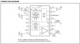
Seeing it has a nice multibit dac in it PCM56, do the AD844 mod for the I/V stage and it will sing.
Go current output from pin 13 and stick a 2 stack AD844 on it and use one of the internal output buffers. for the output.
http://www.diyaudio.com/forums/digital-source/227677-using-ad844-i-v.html
Cheers George
Go current output from pin 13 and stick a 2 stack AD844 on it and use one of the internal output buffers. for the output.
http://www.diyaudio.com/forums/digital-source/227677-using-ad844-i-v.html
Cheers George
Ok I'm a little confused and need to do some more reading. The problem is that some cd players, for example the TDA1549T, have what seams to be an external voltage amp (about 1.6X gain) in addition to the internal I/V. In the case of the tda1541A it has the external I/V and what looks to be a Low Pass filter.
using the current out I'm guessing I don't need the external voltage amp but may need the Low pass filter (as in the tda1541a).
using the current out I'm guessing I don't need the external voltage amp but may need the Low pass filter (as in the tda1541a).
Attachments
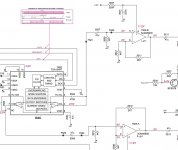
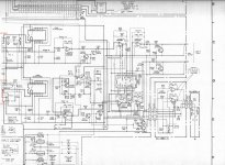
Ok. I now have the manual and have uploaded a scan of the output and block diagram. To me it looks like there is a lot of stuff going on just to get the the line level attenuation (IC308 MM6632A) working. IC302/303 TC74HC4066 Im guessing is the Sample and hold, which I'm guessing I can't remove, following the line from pin 13 it is connected to the DG pin pin 10 of the NPC SM5818 digital filter which is: Deglitch control clock.
From what I can see and what George has said already I can make use of PCM56 pin 13 IOut by taking the signal from pin2 of ic302 and ic303 and use a better I/V stage followed by a good LPF.
Thanks
Tom
From what I can see and what George has said already I can make use of PCM56 pin 13 IOut by taking the signal from pin2 of ic302 and ic303 and use a better I/V stage followed by a good LPF.
Thanks
Tom
Attachments
Last edited:
The 820 looks awfully similar to my 620, same DAC's (2xPCM-56 and laser etc). I upgraded the PS and filtering section in my mine and replaced diodes and lytics for better parts, the 2 caps are bumped from the stock 2200uf and bypassed with a .1uf NOS PIO. I haven't seen the innards for the 820 but there should be a 16.93mhz oscillator clock in there near the output stage. 3 opamps all up in the player, 1 for I/V conversion. All dual opamps but not BB or AD parts some other company. I have a tube clock in mine from a then Prima Luna (and used in the Tjorb Marantz player) and it made it sing. The only problem with 620 atm is that it keeps going back to 00.30seconds on the first track on any disc, might be the laser not sure. Avoid touching the 2 trimpots for laser beam focus and tracking it can mess up your player.
I'd clip the muting transistors near output for first thing to do (and varying taste on listener). My next goal is to add an tube output stage and bypass the opamp's entirely, maybe lampization.
I'd clip the muting transistors near output for first thing to do (and varying taste on listener). My next goal is to add an tube output stage and bypass the opamp's entirely, maybe lampization.
Last edited:
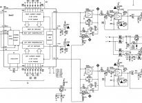
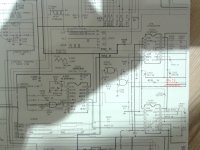
After some reading I still can't work out why DENON engineers placed IC 303 and 302 in this circuit as can be seen it is switched form the De-Glitch pin of the digital filter. Following the circuit they will both switch on and off at the same time, but due to the nand gates will only switch off when the player is switched off. Oddly enough they did not fit this to the DCD-620 which is almost the same player (DefQon). From the PCM56 data sheet it clearly states this circuit is only needed for stereo play back when using a single PCM56 DAC. All i can think of is:
a) the designers didn't read the data sheet properly then rewired the NAND to stay on when they realised it was wrong.
b) its used as a mute circuit
c) the designers are really clever and have managed to get it to work as a high frequency filter or something similar
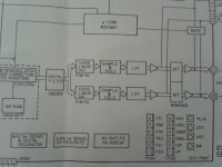
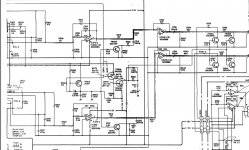
attached is the images of the DCD620 filter and DAC
Basically i intend to:
1 remove this part of the circuit so it will be more like the DCD-620 output
2 remove the head phone circuit
3 remove the variable output circuit
4 as George states use the I out for external IV
5 new op amp for LPF
Thanks Tom
a) the designers didn't read the data sheet properly then rewired the NAND to stay on when they realised it was wrong.
b) its used as a mute circuit
c) the designers are really clever and have managed to get it to work as a high frequency filter or something similar
attached is the images of the DCD620 filter and DAC
Basically i intend to:
1 remove this part of the circuit so it will be more like the DCD-620 output
2 remove the head phone circuit
3 remove the variable output circuit
4 as George states use the I out for external IV
5 new op amp for LPF
Thanks Tom
Attachments

- Status
- This old topic is closed. If you want to reopen this topic, contact a moderator using the "Report Post" button.
- Home
- Source & Line
- Digital Source
- Denon DCD-820 mods upgrades