You done it right. What voltage you have across C11?
I don't have a cap in there at the moment because I took everything out again while I sorted this issue
across the empty pads is 2.49v
got some flux built up in all round that area with all my soldering and desoldering will give it a cleanup as well
edit: just put that cap back in now 3.69v
Last edited:
I don't have a cap in there at the moment because I took everything out again while I sorted this issue
across the empty pads is 2.49v
got some flux built up in all round that area with all my soldering and desoldering will give it a cleanup as well
edit: just put that cap back in now 3.69v
I was not happy that I was getting more than the 2.5v from the output of the ADP151 - obviously something was not right so as I was trying to sort that and clean up some excess solder with a bit of wick I guess left some solder bridges on the pins which meant I ended up with a full short back to the main regulator. I took the ADP out and swapped it with another.
Now I have 2.52v across C11
But still doesn't read TOC
edit: no I don't - its still 3.69v
Should I read basically 2.5V directly at the output of U5? Maybe I misunderstand how regulators work or how to measure their output (Meter across output to gnd)
I'm not getting 2.5v, its the same 3.69v as C11. It is 2.5v at C68
I see on the now unconnected L1 it is 2.5v on the "wrong" side.
Maybe I'm being thick. Tibi I don't understand if C68 is to stabilise U5 why did we take the jumper direct from output to C11. What does the circuit look like around U5? Can you please post (or PM) just the section of this schematic?
SO I am figuring I need 2.5v across C11? I've even double checked the labelling which is definitely ADP151 from Mouser.
Last edited:
SO I am figuring I need 2.5v across C11?
Got the regulator sorted - appears it wasn't grounded properly. So now have a steady 2.5v across C11
BUT currently not reading TOC
Checked with L1 in place again just to be sure that it is all working but no dice
 so seems I can't now forget this mod and go back
Last edited:
Got the regulator sorted - appears it wasn't grounded properly. So now have a steady 2.5v across C11
BUT currently not reading TOC
Checked with L1 in place again just to be sure that it is all working but no dice
Just tested with new mechanism.
Bingo!! Much relieved. Laser might have fried with all the dramas over the weekend? or something has come loose.
Now I just have the "fun" of installing those magic capacitors on the new laser!!
Thanks for all of yours patience with me clogging up the thread.
I came across some reading TOC issue after I added the 1000pf silver mica to the diode. I thought I fried something. But after I removed the SM, it started working again. This happened to the original JVC Shigaclone laser and a brand new one.Just tested with new mechanism.
Bingo!! Much relieved. Laser might have fried with all the dramas over the weekend? or something has come loose.
Now I just have the "fun" of installing those magic capacitors on the new laser!!
Thanks for all of yours patience with me clogging up the thread.
So, something to try before tossing the pickup unit!!
Hi Tibi,
Yeah, I looked at it with a magnifying glass and also measured with a DMM, no short.
I also measured the SM with a LCR meter, it was within the 5% tolerant (1020 pf). Kind
of weird, it didn't happen to my first modified pickup.
I tried a Kemet 1000pf NP0 instead, it operated perfectly. So, my unscientific conclusion is that somehow that Eros MK1837 and that Sangam SM just didn't like each other. A little bit of sharing this strange behavior that I encountered recently.
Hi Tibi,
Back again. I just received a new mech. Removed solder blob, hooked up and started up. Played 1 CD then started same old stuff. The laser lens extends vertically as far as it can twice [toward disc] then shuts down [home position]. I watched the first disc and the tracking vertically was smooth as can be. Again all solder pads and continuities check OK and values in tolerance. 2.2uF laser smoothing cap BG/PK measures 1.8 which is +/-20%. I am not sure what to check next?
best regards,
Steve
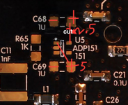
ADP151, problem!
Ok Tibi, I have followed the above and have a problem, my Shiga Black don't want to read TOC anymore either.
L1 removed, Check!
C11, still a mica 1nF, in place, Check!
C68, 10uF tantalum, Check!
C69, 1uF tantalum, Check!
R65, 1kOhm vertical mounted resistor, Check!
Cut the trace accordingly, Check!
Output is nicely 2.52 volt, Check!
But no TOC reading
I start beliving that there is something in the description that is fishy cause according to your answer to Steve, above, U5 should be out over the C68 and then I think that I should be able to measure continuity between output and C68 but I don't.... nill, zip, zero, nada!
Really don't know where to go from here, have checked, double checked and tripple checked all solder points and connections, both with magnifying glass and DMM.
Just to verify the direction for the tantalums, plus is directed into center of the board for both C68 and C69?? It looks like a statement but it is a question. Traced the ground through C11, to C68 and C69 so plus for both tantalums should be in direction in towards center board. Sooo, what now??
Hello,
Note that ADP151 must be 2,5V one.
Please keep C11 in place. C68=10uF tantal is there to ensure ADP151-2.5 stability.
1K is also there to give ADP151-2.5 a slight load.
U5 output is over C68. Measure, do not mount components in "blind".
Regards,
Tibi
Ok Tibi, I have followed the above and have a problem, my Shiga Black don't want to read TOC anymore either.
L1 removed, Check!
C11, still a mica 1nF, in place, Check!
C68, 10uF tantalum, Check!
C69, 1uF tantalum, Check!
R65, 1kOhm vertical mounted resistor, Check!
Cut the trace accordingly, Check!
Output is nicely 2.52 volt, Check!
But no TOC reading
I start beliving that there is something in the description that is fishy cause according to your answer to Steve, above, U5 should be out over the C68 and then I think that I should be able to measure continuity between output and C68 but I don't.... nill, zip, zero, nada!
Really don't know where to go from here, have checked, double checked and tripple checked all solder points and connections, both with magnifying glass and DMM.
Just to verify the direction for the tantalums, plus is directed into center of the board for both C68 and C69?? It looks like a statement but it is a question. Traced the ground through C11, to C68 and C69 so plus for both tantalums should be in direction in towards center board. Sooo, what now??
Hey TIC37, sorry to hear about trouble in paradise.
Despite my reporting success with thi mod earlier, I was premature (only read TOC the once and then nada- thought I must have dreamed it) and so I did end pulling the ADP - messed up the 2 devices I had and so are waiting for some more so I can have another go.
I too got as far as having a strong steady 2.5v but not reading TOC like yourself. I started to think I had an error elsewhere. Anyway, I look forward to reading a solution here.
ADP151 implementation
After some furiosity and despair I must ask L1, what is the function and why does it have to be removed??
As I understand L1 is a ferrite bead filtering HF/RF and nothing more but when removing it I break the circuit if I don't replace with a 0 Ohm resistor or jumper. Sthcoaster reported that with L1 in place the unit read TOC but not without it, shouldn't L1 be replaced to maintain continuity??
I need help and quickly cause I am without nice playing music and I don't survive without my Shiga!
Is there anyone who understand the function and implementation of the ADP151 that can help? I need a
A schematic for the ADP151 implementation would help a lot!
Ok Tibi, I have followed the above and have a problem, my Shiga Black don't want to read TOC anymore either.
L1 removed, Check!
C11, still a mica 1nF, in place, Check!
C68, 10uF tantalum, Check!
C69, 1uF tantalum, Check!
R65, 1kOhm vertical mounted resistor, Check!
Cut the trace accordingly, Check!
Output is nicely 2.52 volt, Check!
But no TOC reading
After some furiosity and despair I must ask L1, what is the function and why does it have to be removed??
As I understand L1 is a ferrite bead filtering HF/RF and nothing more but when removing it I break the circuit if I don't replace with a 0 Ohm resistor or jumper. Sthcoaster reported that with L1 in place the unit read TOC but not without it, shouldn't L1 be replaced to maintain continuity??
I need help and quickly cause I am without nice playing music and I don't survive without my Shiga!
Is there anyone who understand the function and implementation of the ADP151 that can help? I need a
A schematic for the ADP151 implementation would help a lot!
Last edited:
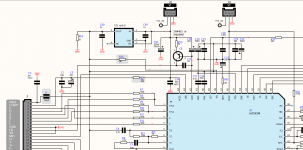
If you use a DMM to check, you will find one side of L1 is connected to R58 (0R) which is connected to pin 58 (VR) of the LA9294M. Therefore, when L1 is in place, it is using the chip's VR. Removing L1 is to decouple the reference from the rest of the circuit. That's my understanding of the L1 mod.
If you use a DMM to check, you will find one side of L1 is connected to R58 (0R) which is connected to pin 58 (VR) of the LA9294M. Therefore, when L1 is in place, it is using the chip's VR. Removing L1 is to decouple the reference from the rest of the circuit. That's my understanding of the L1 mod.
You are right so then it is nessecary to remove L1 but what is affecting the ability to read TOC?
The laser unit is responding normally when I have no disc on the cd-player, laser head is moving up/down searching back and forward to localize TOC area. Laser is ok (verified by telephone) but as soon as a CD is present it can still not read.
Where should I be able to measure the 2.5 volt that I get from ADP151 more than C11 positive side, it should be measurable somewhere else than there?
I also need help to find plus respectively minus for the two caps C68 and C69, I have tried to follow ground plane to both of them but now I realize that I have 2.52 volt on the minus side of C69 while measuring 0 volt on the plus side and that I don't buy. Most likely one or both my caps have to do a 180 degree turn!
Last edited:
C69 is on the input side (pin 1, there is a dot on the pcb) of the adp151. It should be around +5V, referenced to ground.
The output (pin 5) should be around +2.5, referenced to ground.
Probably you forgot to add to the list of mods that you did, but I ask anyway.
Did you connect a wire from output of the adp151 (should measure 2.5) to the +ve side of C11? See post.
Since the cut is immediately after U5 output, I believe C68 and R65 are not needed. Instead, you mount the 10uF tantalum/oscon (new C68) and 1K resistor (new R65) in parallel of C11. Since L1 is not mounted, there will be no voltage reference to C11 and downstream until the output of the adp151 is connected to it.
I hope this will help to keep the spirit going before Tibi responds.
The output (pin 5) should be around +2.5, referenced to ground.
Probably you forgot to add to the list of mods that you did, but I ask anyway.
Did you connect a wire from output of the adp151 (should measure 2.5) to the +ve side of C11? See post.
Hi Steve,
Yes, the board will work just fine with AD151-2,5V reference in place, but will not bring expected sonic improvement.
You need to mount only U5 and C69, cut the U5 output trace immediately after U5 output. Remove L1 bead and grab a wire from U5 output to C11. On C11 mount a 10uF tantalum or oscon in parallel with a good quality 1Kohm resistor - preferably a metal foil one.
This mod will provide a very clean 2,5V reference to pin detector.
You'll love instrument extension and decay after this mod.
Quantum ultra high-grade have this mod inside, It was compared with players above 18000eur and now used as reference along some very big names.
Regards,
Tibi
Since the cut is immediately after U5 output, I believe C68 and R65 are not needed. Instead, you mount the 10uF tantalum/oscon (new C68) and 1K resistor (new R65) in parallel of C11. Since L1 is not mounted, there will be no voltage reference to C11 and downstream until the output of the adp151 is connected to it.
I hope this will help to keep the spirit going before Tibi responds.
Attachments
Probably you forgot to add to the list of mods that you did, but I ask anyway.
Did you connect a wire from output of the adp151 (should measure 2.5) to the +ve side of C11?
Done yes, Check!
From your latest picture it seem that I have the plus and minus correct but how come that I have 2.5 volt on the negative side of C68?? That is buggering me. Still think that there is something fishy with the plus/minus.
U5 function is to provide a very stable 2,5V reference.
The problem that I have observed later is that any difference between ADP151 output and LA9242M Vref pin 58 is translated in "error" voltage and unit will not read TOC.
There are three solutions:
1st solution is to feed separately Vref only to PIN chip, which I already described by removing L1
2nd solution is to keep all parts in place. You mount everything and ADP will "force" output of LA9242M to remain stable at 2.5V
3rd solution is to remove only R58. This will isolate Vref from LA9242M from the rest circuit and will make use only of Vref provided by ADP151.
Regards,
Tibi
Attachments
Easiest solution?
Ok, so my understanding is that since I have now installed R65, C68 and C69 plus the cable between U5 output to C11 positive side..... bla bla.... you know; should be to reinstall L1 or remove R58 if I get your description right? I can in principle use any of the two last solutions to put things in order?
U5 function is to provide a very stable 2,5V reference.
The problem that I have observed later is that any difference between ADP151 output and LA9242M Vref pin 58 is translated in "error" voltage and unit will not read TOC.
There are three solutions:
1st solution is to feed separately Vref only to PIN chip, which I already described by removing L1
2nd solution is to keep all parts in place. You mount everything and ADP will "force" output of LA9242M to remain stable at 2.5V
3rd solution is to remove only R58. This will isolate Vref from LA9242M from the rest circuit and will make use only of Vref provided by ADP151.
Regards,
Tibi
Ok, so my understanding is that since I have now installed R65, C68 and C69 plus the cable between U5 output to C11 positive side..... bla bla.... you know; should be to reinstall L1 or remove R58 if I get your description right? I can in principle use any of the two last solutions to put things in order?
- Home
- Source & Line
- Digital Source
- Shigaclone MKII Black - The builders Thread