one more thing: how do I kill the blue light of the TOC?

I really don't know about which blue light are you talking about.
Could you please be more specific ?
Regards,
Tibi
I mean the led blue light of the counter...
If you want that your LCD not to be illuminated on the back there is P1 500 r print there .
Just unsolder that or jumper that is there.
Board questions
Hi Tibi and all,
I have been comparing the original board to the new one and have a few questions. Let me first apologize if some of these questions have already appeared here, in which case I ask you to direct me to the reply. These are "naive" questions and I have no intention of sounding like I am criticizing any decision made.
1. I cannot find the following equivalent caps on the original shiga: C35, 52, 55, 56, 60, 48, 59 and 11. Neither the inductors L6 and 7. Why were these parts added?
2. C51 (c939) is 100uF in the original schematics and board, not 10uF. Was that intentional?
3. If C48 is in place of c942 than the original value is 220uF , not 10uF.
4. There’s no SMS bypass cap for C10, whereas C953 has C960.
5. Why the section in RED on the pdf attatched eliminated in the new board (R957, C942, C962, and C951*)? I know this refers to the ground of the DAC, but how can we know that eliminating all those elements will not hurt the overall sound? *Note that C951 (on the original schematics) is, as far as I can tell, marked C967 on the original board.
6. Also, why beads instead of zero resistors and why only a few of the original zero resistors? Were they compared for sound or is it only a technical decision (I know that in theory ferrite beads can help reducing noise, but in practice they can hurt the sound in certain situations…)
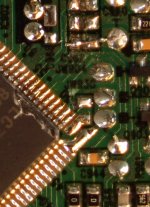
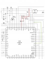
7. The link on LC7860 between EFLG (pin 49) and VLCD1 (pin 40) appears in the original schematics (see pic below marked in GREEN), but it is NOT present in the board (see detail pic of JW930 on the original shiga board). The link has been kept in the new schematics (and I suppose boards too…). Was this intentional?
Since there are so many small difference, I must have missed others. But I would greatly appreciate and thank any of you for any help clarifying this. The sound of the player with the new boards is very different than the sound I had with the original board: better in some regards and worse in others. I would like to depart with a situation on the new board closer to the one I had on the original, and move from there.
Thanks for any help!
Hi Tibi and all,
I have been comparing the original board to the new one and have a few questions. Let me first apologize if some of these questions have already appeared here, in which case I ask you to direct me to the reply. These are "naive" questions and I have no intention of sounding like I am criticizing any decision made.
1. I cannot find the following equivalent caps on the original shiga: C35, 52, 55, 56, 60, 48, 59 and 11. Neither the inductors L6 and 7. Why were these parts added?
2. C51 (c939) is 100uF in the original schematics and board, not 10uF. Was that intentional?
3. If C48 is in place of c942 than the original value is 220uF , not 10uF.
4. There’s no SMS bypass cap for C10, whereas C953 has C960.
5. Why the section in RED on the pdf attatched eliminated in the new board (R957, C942, C962, and C951*)? I know this refers to the ground of the DAC, but how can we know that eliminating all those elements will not hurt the overall sound? *Note that C951 (on the original schematics) is, as far as I can tell, marked C967 on the original board.
6. Also, why beads instead of zero resistors and why only a few of the original zero resistors? Were they compared for sound or is it only a technical decision (I know that in theory ferrite beads can help reducing noise, but in practice they can hurt the sound in certain situations…)
7. The link on LC7860 between EFLG (pin 49) and VLCD1 (pin 40) appears in the original schematics (see pic below marked in GREEN), but it is NOT present in the board (see detail pic of JW930 on the original shiga board). The link has been kept in the new schematics (and I suppose boards too…). Was this intentional?
Since there are so many small difference, I must have missed others. But I would greatly appreciate and thank any of you for any help clarifying this. The sound of the player with the new boards is very different than the sound I had with the original board: better in some regards and worse in others. I would like to depart with a situation on the new board closer to the one I had on the original, and move from there.
Thanks for any help!
Attachments
see attachted
That power section for internal LC78601 sigma/delta dac. I suggest you to document yourself and read LC78601 datasheet.
Regards,
Tibi
Tibi...
What is Bluthor?
Regards
Bluthor is an universal Android/IOS remote control.
A simple interface for any CD player or other device you may want to control via bluetooth.
This can be implemented to almost any device, even those who do not offer any remote control by factory default.
You'll be able to control any Shigaclone with your phone, or almost any CD player you have, amplifier, preamplifier, etc.
Regards,
Tibi
Tibi,
As I mentioned, I am aware that the section is the dac's ps, which is not being used. But the part in red on the pdf refers to the dac's ground. Canceling that circuit might improve or hurt the sound and the only way to know is by comparing both situations. My question was whether you have tried both or if the decision was merely technical.
Any word about the other questions?
Bluthor is an universal Android/IOS remote control.
A simple interface for any CD player or other device you may want to control via bluetooth.
This can be implemented to almost any device, even those who do not offer any remote control by factory default.
You'll be able to control any Shigaclone with your phone, or almost any CD player you have, amplifier, preamplifier, etc.
Regards,
Tibi
I'm confused (again). " Any CD player you have, amplifier, preamp, etc." How do it do this? My system is, the Shiga II, modified Jolida Glass FX Tube DAC, 300B amp, and BK-16 speakers. The only draw back, is no remote volume control for the Jolida DAC, which serves as a preamp. Would this be helpful to me in any way to control the volume of the DAC?
Thanks,
Tony G
As long your Jolida DAC have some push-buttons to control something, bluthor will help you to remote control your DAC - at least source selection and power.
Android client is ready, bluthor firmware and IOS in progress. You may follow bluthor on my webpage or twitter.
Regards,
Tibi
If you will track this circuit you will see that there are some differences and some schematics depend on who implemented :Hi Tibi and all,
I have been comparing the original board to the new one and have a few questions. Let me first apologize if some of these questions have already appeared here, in which case I ask you to direct me to the reply. These are "naive" questions and I have no intention of sounding like I am criticizing any decision made.
- sanyo
- jvc
- other (you will be amazed that are some Oem implementation by others)
Also it helps to observe which variant is with E or with RE at the end.
On the other hand from what I know : Shigaclone MKII Black is the result of Tibi reading and studding all documents from Sanyo about the chips , testing and implementing what he thinks he was understanding from that pdf/docs , but take in mind that he is an graduated experienced engineer with more than 20 years of audio and electronics devices and component (and I mean day by day working on this).
I doubt/ maybe he will share with the secrets he found about those chips without you putting the right question , but from the forum i see that from time to time he share some of his great experience accumulated over the years.
On the other hand : i am the owner of all type of Shiga beginning with the JVC type that first was discovered by Peter Daniel and then Vicol Shiga 1 and Shiga II and the last one Shigaclone MKII Black and let me be clear :
i see no downs in the Shigaclone MKII Black in every aspects.
JVC SHIGA modded (from the original modding thread) is like a little nothing when listen side by side with Shigaclone MKII Black , this is what I am hearing and this are my thoughts .
Hi Danzup,If you will track this circuit you will see that there are some differences and some schematics depend on who implemented :
- sanyo
- jvc
- other (you will be amazed that are some Oem implementation by others)
Also it helps to observe which variant is with E or with RE at the end.
On the other hand from what I know : Shigaclone MKII Black is the result of Tibi reading and studding all documents from Sanyo about the chips , testing and implementing what he thinks he was understanding from that pdf/docs , but take in mind that he is an graduated experienced engineer with more than 20 years of audio and electronics devices and component (and I mean day by day working on this).
I doubt/ maybe he will share with the secrets he found about those chips without you putting the right question , but from the forum i see that from time to time he share some of his great experience accumulated over the years.
On the other hand : i am the owner of all type of Shiga beginning with the JVC type that first was discovered by Peter Daniel and then Vicol Shiga 1 and Shiga II and the last one Shigaclone MKII Black and let me be clear :
i see no downs in the Shigaclone MKII Black in every aspects.
JVC SHIGA modded (from the original modding thread) is like a little nothing when listen side by side with Shigaclone MKII Black , this is what I am hearing and this are my thoughts .
Thanks for the reply! The comment about the various schematics/ implementations of JVC and Sanyo was helpful; it makes sense because I can see some differences between the schematics and the boards I have. On the other hand, I had no idea that there were secrets about Tibi's implementation. I just wanted to understand the differences I pointed out.
In any case, I want to be in good terms with Tibi (who has always been very attentive with me) so I apologize to him and to anyone here if my questions were offensive. I don't participate very often on forums and when I do I tend unload too much too fast. My bad.
Hi Tibi and all,
I have been comparing the original board to the new one and have a few questions. Let me first apologize if some of these questions have already appeared here, in which case I ask you to direct me to the reply. These are "naive" questions and I have no intention of sounding like I am criticizing any decision made.
1. I cannot find the following equivalent caps on the original shiga: C35, 52, 55, 56, 60, 48, 59 and 11. Neither the inductors L6 and 7. Why were these parts added?
2. C51 (c939) is 100uF in the original schematics and board, not 10uF. Was that intentional?
3. If C48 is in place of c942 than the original value is 220uF , not 10uF.
4. There’s no SMS bypass cap for C10, whereas C953 has C960.
5. Why the section in RED on the pdf attatched eliminated in the new board (R957, C942, C962, and C951*)? I know this refers to the ground of the DAC, but how can we know that eliminating all those elements will not hurt the overall sound? *Note that C951 (on the original schematics) is, as far as I can tell, marked C967 on the original board.
6. Also, why beads instead of zero resistors and why only a few of the original zero resistors? Were they compared for sound or is it only a technical decision (I know that in theory ferrite beads can help reducing noise, but in practice they can hurt the sound in certain situations…)
7. The link on LC7860 between EFLG (pin 49) and VLCD1 (pin 40) appears in the original schematics (see pic below marked in GREEN), but it is NOT present in the board (see detail pic of JW930 on the original shiga board). The link has been kept in the new schematics (and I suppose boards too…). Was this intentional?
Since there are so many small difference, I must have missed others. But I would greatly appreciate and thank any of you for any help clarifying this. The sound of the player with the new boards is very different than the sound I had with the original board: better in some regards and worse in others. I would like to depart with a situation on the new board closer to the one I had on the original, and move from there.
Thanks for any help!
Marcelo,
My first observation is that you are posting questions about Shiga MKI in Shiga MKII thread. Some of your questions have been already discussed, but Shiga si a huge thread ...
As you may noticed Shiga MKI is not a reverse engineering of JVC EZ31. In fact it do not use same chips. It is easy to see that JVC EZ31 make use of a cheap chinese driver CSC1469XH while Shiga use of original Sanyo LA6541.
On other hand, if you try to follow JVC EZ31 schematic on your EZ31 board you'll end more confused, as there are huge differences. Also, if you take Sanyo MCD-ZX250 schematic, you'll end up even more confused, as there same IC's are differently implemented.
Even more, as Dan mentioned, there is LA78601E and LA78601RE which are same chips with different pin terminations.
Now, your questions:
1. As i already said, Shiga MKI and MKII are a new design. Some capacitors have been added in order to compensate new PCB layout and to proper implement new circuit design.
2. Yes, this was intentional. Shiga have CLC filter in place while JVC EZ31 not.
3. C48 is NOT in place of C942. C942 is part of dac decoupling. In order to reduce noise and enhance LA78601RE performance, Shiga MKI and MKII do not make use of internal dac structure. This was completely eliminated from design together with analog output.
4. Shiga have a better ground layout and that cap was moved in the right place, near to LA9242M pin 64. It is called C14 and his value was properly adjusted to 10nF instead 100nF.
5. I already responded to this question on pct. 3
6. "why only a few of the original zero resistors" ? I really hope you are joking here.
Because Shiga is a two layer PCB and offer a far better layout.
Zero resistors have been used in JVC EZ31 design in order to facilitate connection between traces. That all, no voodoo, no special effects, no sonic improvement, just some silly zero ohm resistors.
7. Here I'm sending you again to datasheet.
Pin 49 is EFLG. "Monitor for C1, C2, single, and double error corrections.
49 EFLG O (Note that this output is only provided in test mode. This pin outputs a low level during normal Low output mode operation.)"
Pin 40 is VLCD1 and provide LCD bias power supply. Not mentioned in datasheet, but this pin is also internally connected.
Why I should directly connect these two pins ? Or just simply providing right potential is enough ?
And yes, beside a better circuit design and PCB layout there are other differences, like component selection. This make Shiga MKII so great and people who have compared to JVC EZ31, Shigaraki or Flatfish are trilled by Shiga performance.
Hope you are satisfied with my answers and I'm here to support you in getting the best from this design.
Regards,
Tibi
Last edited by a moderator:
- Home
- Source & Line
- Digital Source
- Shigaclone MKII Black - The builders Thread