A high C8 value will make tracking very slow.
Personally I would use a generator to burn that capacitor. Set a generator at 1KHz 10Vpp square wave and burn that cap as long you like. On the same time you can see on a scope burning effect as the square fronts will change in time.
If you do not have a generator connect the cap at the Shiga trafo output, before rectification.
Regards,
Tibi
Continuation from http://www.diyaudio.com/forums/digi...mkii-black-builders-thread-6.html#post3929218
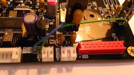
In order to power miniregs you need to make a strap from 8V common point to each regulator. Miniregs will be in series after main 8V regulator from power supply board. Don't forget that L5 and L9 must be removed.
Why a wire and not another elegant solution ?
Because I wanted to leave board open to another regulators as well.
Miniregs are LDO and can be cascaded after main PS.
Other super-regulators: tentlabs, alr, burson, belleson etc are not LDO and you need to power them from a separate higher PS.
GND from any other external power supply must be connected at J6.
Regards,
Tibi
Attachments
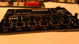
control and display board
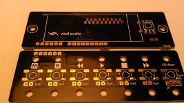
Main board is ready now. All to do is to connect 18wire flat cable to control and display board.
This is how to build control and display board.
You can start soldering all smd parts and leave at the end push-button switches.
I started with switches. Same technique, solder one pad and align all switches.
Regards,
Tibi
Attachments
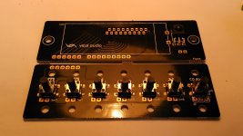
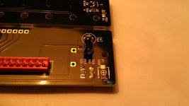
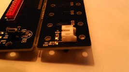
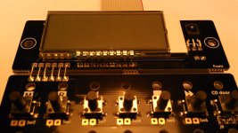
Solder other parts except LCD display and back-light. You need to solder these only after flat cable is connected.
Nothing fancy for C67. This cap is decoupling for infrared sensor.
P1-500ohm is optional. Mount one if you like to adjust back-light intensity.
Mounting J9 as in below picture (over Q4) will leave access open to mounting hole.
Regards,
Tibi
Nothing fancy for C67. This cap is decoupling for infrared sensor.
P1-500ohm is optional. Mount one if you like to adjust back-light intensity.
Mounting J9 as in below picture (over Q4) will leave access open to mounting hole.
Regards,
Tibi
Attachments
Last edited by a moderator:
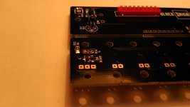
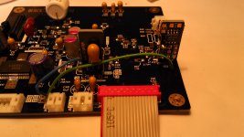
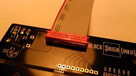
In case you want to use control board connected to display board solder small wires between boards.
Connect flat cable on main and display board. Best way to do this is to use two flat small pinewood pieces. Place one under connector and another over top cover connector. Press this till you hear connector clicking. You may use a big pliers like in picture.

Regards,
Tibi
Connect flat cable on main and display board. Best way to do this is to use two flat small pinewood pieces. Place one under connector and another over top cover connector. Press this till you hear connector clicking. You may use a big pliers like in picture.
Regards,
Tibi
Attachments
Last edited by a moderator:
Listening impressions ..
For me this Black Shiga MKII is simply the best CD Player / Transport I have in my home ever.
The sound stage , after modding is huge, the high , middle and low registries of sound are correct and sweet , the pleasure of listening to my favorite CD is at the most enjoyable peak .
After all I am very pleased by my Shiga and recommend to all that want to build something wonderful to listen real and pure music.
Happy diy to you all .
Will be back with pictures with case finished .
P.S. : I am not good at writing and impression , hope you will understand this .
improving SFP101N
Following modification address and improve laser operation of SFP101N-16P Sanyo cd mechanic.
Undoubtedly SFP101N-16P is a very good CD mechanic, but this can be improved further with a simple trick.
Modification is simple but require attention and a steady hand.
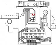
We are going to replace a ceramic X5R 100nF which decouple laser diode. This is the worst MLCC type with a huge piezoelectric effect and capacity variation with voltage and temperature is also very high.
As this position is in a very sensitive area, where vibrations and shocks are quite important, I expected some improvement.
Result is astonishing, above all my expectations.
This is a highly recommended modification.
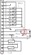
In below pictures I have marked with red capacitor position on schematic and board.
Regards,
Tibi
Following modification address and improve laser operation of SFP101N-16P Sanyo cd mechanic.
Undoubtedly SFP101N-16P is a very good CD mechanic, but this can be improved further with a simple trick.
Modification is simple but require attention and a steady hand.
We are going to replace a ceramic X5R 100nF which decouple laser diode. This is the worst MLCC type with a huge piezoelectric effect and capacity variation with voltage and temperature is also very high.
As this position is in a very sensitive area, where vibrations and shocks are quite important, I expected some improvement.
Result is astonishing, above all my expectations.
This is a highly recommended modification.
In below pictures I have marked with red capacitor position on schematic and board.
Regards,
Tibi
Attachments
Last edited by a moderator:
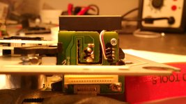
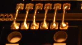
As I said the cap is 100nF X5R.
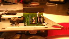
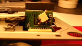
Almost any capacitor will be better, but must be small enough do not affect mechanic operation. Also big caps with long leads are out discussion here. The cap must be as close as possible to laser.
My choice is Arcotronics MKT. It is good, cheap, have exceptionally low ESR, and small enough to be soldered directly on laser pins.
Another candidate could be VISHAY-RODERSTEIN MKP-1837.
Here is the cap in his new job.
Regards,
Tibi
Attachments
Last edited by a moderator:
Now about the sound. ")
I expected some improvement at least in tracking and reading, but the result is astonishing.
This is a completely new dimension ...
The bass ... Wow, the bass get a lot of weight and each instrument have more body. Voices are here, full of deepness and every detail is full of harmonics, much better defined.
I consider this modification the most important and the most effective so far. Give it a try and let me know your results.
Regards,
Tibi
Last edited by a moderator:
Got me all excited I will try this today. I m really curious how much better the transport can be
You think these will be ok? I have a few left
BFC247076104 Vishay / BC Components | Mouser
otherwise it will have to be
BFC246756104 Vishay / BC Components | Mouser
Sorry for not testing the black pcb+miniregs yet
I will try this today. I m really curious how much better the transport can be You think these will be ok? I have a few left
BFC247076104 Vishay / BC Components | Mouser
otherwise it will have to be
BFC246756104 Vishay / BC Components | Mouser
Sorry for not testing the black pcb+miniregs yet
Got me all excited
You think these will be ok? I have a few left
BFC247076104 Vishay / BC Components | Mouser
otherwise it will have to be
BFC246756104 Vishay / BC Components | Mouser
Sorry for not testing the black pcb+miniregs yet
No, these are too big.
You need a small cap, low voltage MKT/PET, who can be mounted directly over laser.
The length of leads is important as well.
This is what I have used.
R82DC3100Z350J - ARCOTRONICS - CAP, FILM, PET, 100NF, 63V, RAD | Farnell România
Regards,
Tibi
Aha, than the picture is wrong. Go for BFC247076104.
FK28X7S2A104K TDK | Mouser is another ceramic X7S bastard. This will kill your transport in a different way.
As I already mentioned Vishay MKP-1387 could be a good candidate, maybe the best.
Vishay R. Film Caps
Regards,
Tibi
Here Wima equivalent to Arcotronics.
MKS2C031001A00KSSD - WIMA - CAP, FILM, PET, 100NF, 63V, RAD | Farnell România
Regards,
Tibi
MKS2C031001A00KSSD - WIMA - CAP, FILM, PET, 100NF, 63V, RAD | Farnell România
Regards,
Tibi
Now, I'm very tempted to replace another two small X5R caps.
One is Vcc decoupling on photo-detector and another one is Vref decoupling for the same photo-detector. Unfortunately these must be small enough to fit the space and as close as possible to photo-detector chip. I'm looking for a solution ... will see.
Regards,
Tibi
One is Vcc decoupling on photo-detector and another one is Vref decoupling for the same photo-detector. Unfortunately these must be small enough to fit the space and as close as possible to photo-detector chip. I'm looking for a solution ... will see.
Regards,
Tibi
Thought this is a quick upgrade I'm going to do here directly but I have 10nf Vishay MKP-1387
Maybe the Black Gate NX HI-Q 0.1 uF an option? This one is very small ...
Regards,
Rudy
It is obvious that the 100nF X5R cap used in SFP101N mechanism is a choice of low ESR at ultra low cost.
As a manufacturer, you can not keep the price low if you start to drop foil capacitors into your product.
To get the right value I should run a FFT these days.
You may test with 10nF Vishay MKP-1387.
BG NX are not intended for decoupling. Inside NX are two caps connected in series and ESR will be higher than most foil caps.
My recomandation is to keep noise low with a small MKT/MKP/MKS/PET cap.
A proper sized 10nF silver-mica could be best noise killer.
Regards,
Tibi
- Home
- Source & Line
- Digital Source
- Shigaclone MKII Black - The builders Thread