Hi
sorry but it is not quite clear from the thread title
"Master clock and isolator for the MiniDSP USBStreamer"
Master clock OK
Isolator OK
Mini DSP ? probably part of the device?
USB streamer? Which usb streamer? like integral part of the device OR something else?
thanks
")
sorry but it is not quite clear from the thread title
"Master clock and isolator for the MiniDSP USBStreamer"
Master clock OK
Isolator OK
Mini DSP ? probably part of the device?
USB streamer? Which usb streamer? like integral part of the device OR something else?
thanks
Hi Zoran,
Sorry, I just assumed that MiniDSP was a well known name on this forum. They have their own section under Manufacturers.
Anyway, this is the one I am talking about:
USBStreamer | MiniDSP
Sorry, I just assumed that MiniDSP was a well known name on this forum. They have their own section under Manufacturers.
Anyway, this is the one I am talking about:
USBStreamer | MiniDSP
The V3 has been up running for quite some time now. I made a V4 of the design, which includes a mux, to allow a better handling of the situation where there is no power on the isolated (ADC/DAC) side and therefore no external MCLK.
But before I ordered PCB's for the V4, I decided to add another option, which makes it possible to use either a x½ or a x2 clock (relative to the normal 24.5/22.5 MHz MCLK). I hope to get the PCB in a few days and hopefully I will find the time to mount it sometime next week.
I have attached an updated block diagram, showing V5 with the PLL and the mux.
When there is no MCLK from the isolated side, the mux will select the lower input, which comes from the USBStreamer. This feeds the original MCLK back to the USBStreamer, hopefully avoiding a lock up situation, where the PC driver could hang.
The PLL can either be controlled using a jumper on a pin header, or a front panel switch can be added. I have also included a bypass resistor, so that the PLL does not have to be mounted.
Attachments
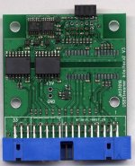
Here is a scan of the V3. V5 will be very similar.
On V5 I decided to remove also the local 3.3V regulator, since it can be supplied from the ADC/DAC board. The optional PLL is placed in this area, just below the middle of the PCB. In the top area the added mux has been squeezed in.
The V3 has space for additional isolators, but, as shown in the picture, I haven't mounted these, since I only needed a 2-channel version for now. And I have a limited number of isolators on hand.
Attachments
V5 is now up and running. The mux on the USB side seems to work as intended. So when the power on the isolated side is turned OFF, the USBStreamer just gets its own MCLK back and there is no lock up problem. The transition seems to be smooth with no (apparent) interruption in the playback.
The PLL has only been tested briefly, but it is in the circuit and seems to work OK. Next step is to try it with a 12.288MHz clock input and X2 operation, so that the USBStreamer will still get 24.576 MHz.
I don't have a 45/49 MHz design to test it with, but I don't think that this will be a problem.
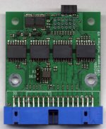
On this version I mounted all isolators to get 8 channels in/out. I decided to use one of the cables, which came with the USBStreamer, to connect it to the USBStreamer. On the previous versions I used a connector with an extension. The cable provides more flexibility in terms of positioning the interface and the USBStreamer in a box.
The PLL has only been tested briefly, but it is in the circuit and seems to work OK. Next step is to try it with a 12.288MHz clock input and X2 operation, so that the USBStreamer will still get 24.576 MHz.
I don't have a 45/49 MHz design to test it with, but I don't think that this will be a problem.
On this version I mounted all isolators to get 8 channels in/out. I decided to use one of the cables, which came with the USBStreamer, to connect it to the USBStreamer. On the previous versions I used a connector with an extension. The cable provides more flexibility in terms of positioning the interface and the USBStreamer in a box.
Attachments
Yahoo, just got my USBStreamer yesterday...wow, it is small !!! I would be very, very grateful if you would sell me one of your boards; of course an assembled board for 6 channels would be ideal, but I can deal with a kit or a bare board as well. If you want to take this discussion private my email is "amitaru" at google mail.
thank you, Alex
thank you, Alex
1. For very small quantities I can handle sales of the bare PCB. For larger quantities or assembled boards I need to figure out a way to handle it.
2. I don't think it is necessary to push things further in that direction. With the existing design it is possible to make a "perfect" solution already
The USB side of the design is powered entirely from the host side (typically a PC). It does not need to be particularly clean. It just needs to provide a reasonably stable supply voltage at the current used by the USBStreamer + a few mA for the USBStreamer Interface.
The isolated side needs a 3.3V supply from the converter board or some other source. What matters here is that the MCLK of the ADC/DAC board (feeding the converters) is very clean. If we assume for a moment that we can make a perfect clock, the ADC/DAC can be clocked with a perfect timing. If some jitter is added on the way to the USBStreamer Interface/USBStreamer, it doesn't matter. As long as the converters get the perfect clock.
If the MCLK determines the exact timing of the conversion process everything will be perfect.
If the SCLK (which comes from the USBStreamer) determines the exact timing, the SCLK should be resynchronized on the ADC/DAC board, using the MCLK. The need for this depends on the ADC/DAC used.
Interesting project! I am also planning a multi-way DSP setup and was intending to use USB Streamer as the interface. I could only assume the clocks were all derived by PLL since the only on-board crystal appeared to be the 12MHz USB one. So, the benefit of generating new, stable clocks is evident.
I might be interested in a board, or two, since I need 6 channels but will build my interface to support up to 8. Bare board would be fine for me. I'm only unsure if I can find the space to generate and distribute the clocks on my DAC board, requires another re-design then
I might be interested in a board, or two, since I need 6 channels but will build my interface to support up to 8. Bare board would be fine for me. I'm only unsure if I can find the space to generate and distribute the clocks on my DAC board, requires another re-design then
Yes, the clocks on the USBStreamer is generated from the 13 MHz clock (not 12 MHz). It seems to be multiplied in the XMOS and divided to 300 Hz. The 300 Hz is then used in a PLL to generate the MCLK. This whole process adds quite a lot of jitter, which was the reason I decided to make an interface, which uses a clean external clock.
If you take a couple of the very good NDK oscillators (NZ2520SD series), the clock circuit won't take up much space. These oscillators are 2.5x2mm. And having the clock oscillator close to the DAC will generally be better.
You could also choose to use the V1 of the PCB, which you can see in post #2. As long as only a DAC is connected (no ADC with data in the reverse direction) the V1 should be OK.
I have also made a layout for a design with the faster isolators and no octal flip-flop (the 20 pin SSOP, which is bridged by a few small wires in the picture shown in post #2). I have not sent the V2 for manufacturing, since I decided to move to a solution without on-board oscillators. If there is an interest I could get some PCB's of the V2. It will take a couple of weeks after ordering.
I have just made a test of the V5 with clocks of 11.2896/12.288 MHz, using the PLL to generate 22.5792/24.576 MHz. It works as intended.
No, the SCLK and LRCK still come from the USBStreamer. So the USBStreamer is still the I2S master.
Only the MCLK is "injected" into the USBStreamer from outside. This part is not described in the manual, since the USBStreamer was not designed for that. It requires a HW modification.
Only the MCLK is "injected" into the USBStreamer from outside. This part is not described in the manual, since the USBStreamer was not designed for that. It requires a HW modification.
Hello Jens,
I have just received a USBStreamer myself and would also like to use it with an external clock.
Any chance to get one of you bare PCBs? V5 would be great but since I am not fixed on a specific implementation yet, any would work.
I have done SC70 before so am reasonably confident to do the soldering.
How involved are the mods to the USBStreamer?
Thanks,
Sönke
- Status
- This old topic is closed. If you want to reopen this topic, contact a moderator using the "Report Post" button.
- Home
- Source & Line
- Digital Source
- Master clock and isolator for the MiniDSP USBStreamer