Say we were using an external battery to power our off board clock
we would have a twisted pair bringing power to the clock from as short a distance as possible?
the clock signal will need to be connected by a short coax cable and grounded on both sides?
is this signal gnd?
The battery neg would also need to be connected to juli@ or motherboard gnd?
would there be any benefit by having multiple gnd connections between clk ps and motherboard juli@ gnd?
thanks for the help
nige
We are talking digital and low level analogue, there is or should be only one ground....
Digital signals such as clocks need a return path, as do all electrical signals... This is critical to signal integrity, thus the clock requires two wires from the daughter board to where it connect to the main board, as close as possible... To do anything else is wrong.
The clock daughter board Ground want to be at the same potential as the main board ground this implies a low impedance connection for power as well as the return path connection for the clock. If you had more signals going from the daughter card to the main board EACH of these signals would require their own separate return path to do the job properly, either as a coax for each signal or a twisted pair.
The method shown for the motherboard as I have already commented on is the worse possible scenario I could imaging for adding an off board clock, It is bad advice like this that does not help and to be perfectly honest I think people doing this are charlatans feeding peoples insecurities about clocks and not having a full understanding of what they are doing, on the video it looks like he has no ESD protection again critical if you are going to mess about with your motherboard... Also what he does would add quite severely to the ovelall system noise levels and again thus have an influence on signal integrity. There are good examples of add on clock upgrades such as Tentlabs, at least you are told how to connect it properly.
Attached are some files I have put together with links to wider reading regarding PCB layout and system interconnection that I give out to people wanting to dig a bit deeper into all this, basic current flow and rely 2 grounds and currents would be a good place to start...
Attachments
Another interesting link I have just found....
http://www.celectronics.com/seminar/sample/IEEE11-9-05.pdf
Think RETURN PATH all the time every signal has to have one......
http://www.celectronics.com/seminar/sample/IEEE11-9-05.pdf
Think RETURN PATH all the time every signal has to have one......
This is a good discussion. Please keep it up. I will definitely be revisiting my Juli@ card once I finish my 5A x 12/5/3.3V regulated linear supply. (I'm waiting for their boards to arrive. I've completed the necessary in-rush limiter and ATX power monitoring/sequencing control board.) Now I am worried because I have removed the resistor associated with each crystal as well...
This is a good discussion. Please keep it up. I will definitely be revisiting my Juli@ card once I finish my 5A x 12/5/3.3V regulated linear supply. (I'm waiting for their boards to arrive. I've completed the necessary in-rush limiter and ATX power monitoring/sequencing control board.) Now I am worried because I have removed the resistor associated with each crystal as well...
theres motherboards that work perfectly without ATX power monitoring/sequencing control
granted not as safe though
gigabyte
h97m d3h
z97m d3h
MSI B85M G43
Z87M G43
H81M-P32
H81M-P33
asus
h81i-plus
im just fearful
putting in two botched clocks in a juli@ and then putting that into a pc with two botched clocks is bound to have issues
even at the moment connecting devices to ports sometimes causes glitches
i assume this is grounding
if the original oscillator signal is say 500mv will the replacement clock need to match that?
if so how do you reduce ?
attenuation?
well i can say the Juli@ is working well and has been for the last year or so. Perhaps it can be improved with better GND return and this is something worth examining but it doesn't sound bad at all now and has never failed me. (Whether that's an indication that fussing with the clock is a waste of time I have no idea.)
I've learnt a good deal since I attempted to remove the two crystals from the Juli@ (although I would hasten to add that I think removing these isn't an easy task for anyone other than someone who has done it a number of times before).
An ATX power control board isn't so hard to implement, why not use one? (For me it was quite a learning project but I had very good tutoring particularly from Mark Johnson.) The most complicated part of mine is the measurement amplifier I added in order to measure the noise on the power rails. (It accounts for almost all the parts between the 12V input and the 3V3 input.) Having just said that, I've not been able to test the module yet as I don't have a 3 voltage bench PSU. I have to complete my PSU rails first. The board is 80mm x 85mm and the core of the power monitoring and sequencing is performed by a TPS3510.
As for "putting in two botched clocks" well I agree I botched the removal of the crystals but the trace damage was repaired. We are, of course, debating the correct wiring for the return path and whether this can be improved. I'm afraid I'm not sure your last questions make sense. Perhaps you can elaborate.
Attachments
Last edited:
As an aside, with respect to motherboards I am only interested in mini-ITX ones that have a well-placed ATX power socket, HDMI, either mSATA or m.2 for the OS and nothing to interfere with the passive cooling. I am currently using an ASRock Z87E-ITX but may well replace this in my current build.
But let's try to keep this thread to modding the Juli@...
I'm happy to chat offline or in the respective threads for my ATX control board and my PSU if anyone wants.
But let's try to keep this thread to modding the Juli@...
I'm happy to chat offline or in the respective threads for my ATX control board and my PSU if anyone wants.
Last edited:
ok
no probs ill find your mobo ps thread
no i meant is if the original oscillator signal had a rise or fall of say 500 mvolts
but your new replacement oscillator has rise and fall much higher
does it have any implications or if so whats the solution
btw was referring to my botch work, not yours
no probs ill find your mobo ps thread
no i meant is if the original oscillator signal had a rise or fall of say 500 mvolts
but your new replacement oscillator has rise and fall much higher
does it have any implications or if so whats the solution
btw was referring to my botch work, not yours
Interesting thread. What about moving the analog part outside the case? Would it be possible to handle the cabling issues or would anything gained be eaten up? What about shielding the analog part inside the case? Heath problems might arise and of course it would be easy to create shorts...
Regards
Regards
Or maybe everyone is happy with built in chips on the mothaboard? ") Would that be a surprise? Yes, to me...But then again everyone might have found a better, more tweakable board and haven't had the time to communicate it? If the industry tells us we are at the brink of technology then there is probably a long way to go. What they tell us is that they are content with the prevailing technology as it gives enough income - nothing else.
Would that be a surprise? Yes, to me...But then again everyone might have found a better, more tweakable board and haven't had the time to communicate it? If the industry tells us we are at the brink of technology then there is probably a long way to go. What they tell us is that they are content with the prevailing technology as it gives enough income - nothing else.
Would that be a surprise? Yes, to me...But then again everyone might have found a better, more tweakable board and haven't had the time to communicate it? If the industry tells us we are at the brink of technology then there is probably a long way to go. What they tell us is that they are content with the prevailing technology as it gives enough income - nothing else.Hey Turbon...
The analog portion of a Juli@ does not move very far from the digital portion without degradation because the signal connections are I2S. Also, the sourcing chips (both on the digital portion and the analog portion) don't have a strong signal drive. Lengthening the connection just adds jitter and worsens the sound.
My experience fitting alternative I2S-input DAC cards to the Juli@ is that the shorter and more direct one can make the connections, the better the sound.
One could consider LVDS for a longer I2S connection, but that process adds jitter too. If doing a play-back only setup, you could do that with an async reclocker like Ian's FIFO or an async DAC like most ES9018 setups.
As far as shielding, I suggest reducing the sources of interference first. Linear supplies for the Juli@ and for the host computer go a longer way towards resolving issues than shielding in my experience. I've come to believe it is better to eliminate sources of noise rather than try to filter or shield from them.
That said, a Juli@ with replacement regulators (Dexa) and separate power (+5v, +-12v) on a computer with a 12v supply for the CPU and another 12v supply to a PicoPSU (which does have DC-DC converters, but is less noisy than most full SMPSs and almost all computer supply SMPSs) can sound pretty darned good.
As for alternatives, there's not much out there in the PCI/PCI-e world. I have not been able to confirm it, but I suspect that interface is limited to 24bit or 32bit/192kHz as I've not found any alternatives that go above those. Pink Faun makes what appears to be the best alternative available today and it looks to be very competently executed, but it is about 3x the cost of a Juli@. And it still does not go beyond 32bit/192kz. Nowadays, to do good filtering, one really needs 384kHz!
As for PCI versus PCI-e, most motherboards are now PCI-e with an on-board bridge providing a PCI slot where fitted. One might think a PCI-e Juli@ on these boards into the PCI-e slot would avoid that additional processing. But the PCI-e Juli@ has a PCI-e->PCI bridge on the digital portion, so that processing is just moved from the motherboard to the Juli@!
Greg in Mississippi
P.S. I don't much care for the chips on the motherboard as an I2S source. At best one can use a low-power board like an R-Pi or BeagleBone Black where an I2S feed is available AND use an Isolator/Reclocking interface, with synchronous (like Acko's S03) probably the best, but where you can't feed the downstream clock back to the source (like on an R-Pi or a Juli@), an async setup (like Ian's FIFO with Isolator) works well.
Linear supplies for the Juli@ and for the host computer go a longer way towards resolving issues than shielding in my experience. I've come to believe it is better to eliminate sources of noise rather than try to filter or shield from them.
That said, a Juli@ with replacement regulators (Dexa) and separate power (+5v, +-12v) on a computer with a 12v supply for the CPU and another 12v supply to a PicoPSU (which does have DC-DC converters, but is less noisy than most full SMPSs and almost all computer supply SMPSs) can sound pretty darned good.
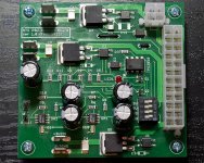
I have just completed a linear ATX PSU build with 5A+ capable 'super reg' boards providing 12V, 5V and 3V3. As noted earlier in this thread, I upgraded the clocks on my ESI Juli@ (although I need to look again at the GND return for this) and this clock is powered from the 12V reg (and has another built in high-quality reg on the clock upgrade).
Greg, how do you power the ESI Juli@ XTe independently of the motherboard? (I'm only using the digital portion of the card.)
Last edited:
Hi everyone!
This post a little old but I am trying to power esi juli@xte with hybrid power supply.
I use riser cable and 12v battery and dc to atx converter.
I cut the 12v 3.3v cables on the riser cables.
But I couldn't be sure about ground cables.
Which grounds should I connect to new PS?
And should they be connected to computer psu at the same time?
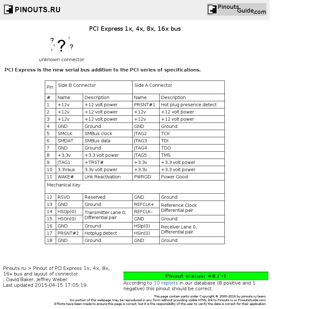
To power the card separately, you need to supply 12v and 3.3v to all of those lines on the riser cable. These lines should ONLY be connected from the separate power supply to the card, not to the computer.
Then you also need to connect the ground from the separate power supply to the ground lines on the riser card. These lines must stay connected to both the card AND the computer, you are just adding a connection to them from the separate power supply.
Best on your mod... let us know how it works.
Greg in Mississippi
To power the card separately, you need to supply 12v and 3.3v to all of those lines on the riser cable. These lines should ONLY be connected from the separate power supply to the card, not to the computer.
Then you also need to connect the ground from the separate power supply to the ground lines on the riser card. These lines must stay connected to both the card AND the computer, you are just adding a connection to them from the separate power supply.
Best on your mod... let us know how it works.
Greg in Mississippi
Should I connect all the grounds or Is there something like signal ground vs power ground?
Thanks a lot..
- Status
- This old topic is closed. If you want to reopen this topic, contact a moderator using the "Report Post" button.
- Home
- Source & Line
- Digital Source
- Tweaking an ESI Juli@ XTe card