I'm still learning how to use the scope...
Test was done using the RF pad on the bottom of the transport PCB. Not sure if the ground point was an issue or ??? Could easily be doing something wrong. Checked the scope again and it is set for 5mV/DIV. Also not sure if the 10x probe makes any difference. My friend was over and we started by using the scope on a AA NiMH battery and got what seemed to be a reasonable deflection on the scope, roughly 1.3V, which seemed to accord with the scope settings. Also saw the pattern move up/down, seemingly correlated to an out-of-round disc. Pattern seemed stable in the horizontal.
Test was done using the RF pad on the bottom of the transport PCB. Not sure if the ground point was an issue or ??? Could easily be doing something wrong. Checked the scope again and it is set for 5mV/DIV. Also not sure if the 10x probe makes any difference. My friend was over and we started by using the scope on a AA NiMH battery and got what seemed to be a reasonable deflection on the scope, roughly 1.3V, which seemed to accord with the scope settings. Also saw the pattern move up/down, seemingly correlated to an out-of-round disc. Pattern seemed stable in the horizontal.
@12bass
Given that the output OPAMPS of the CD player are sat at 0v, you could bypass output caps altogether.
I believe I also mentioned previously in this thread that you would likely glean a small audible benefit by removing those muting transistors on the output and replacing them with a relay.
It would also be useful to reduce the output impedance of the player by bridging R375 / 376 / 377 / 378 (220 ohm) and replacing R383 / 384 with something in the region of 50 ohm to 75 ohm (not critical)
You would of course have to remove the muting transistors to effect the resistor mods though, although you could likely bridge R383 / 384 which would usefully reduce the output impedance to ~ 440 ohms.
The output impedance is ~ 1k ohms at the moment, and that will definitely cause some interaction with high capacitance interconnects.
This is something you could experiment with easily enough. Bypass the entire muting stage just by lifting C377 / C378 and taking the output directly from the OPAMP via a 56 ohm resistor (to separate RCA jacks of course - or also lift R383 / 384) so a 56 ohm resistor from the OPAMP output to the RCA side of R383 / 384...
I doubt very much you'll experience any extraneous noises without the muting stage as muting is performed elsewhere anyway - those final muting transistors will be in place to avoid switch on pops from the OPAMPS.
Yes, the amplitude looks more like 1.2 Vp-p. A bit more actually. Is the focus off on your 'scope by chance? If not, then maybe we are seeing an unstable eye pattern. The vertical and horizontal aspects could be moving a lot, quickly.
I would say that the laser power output is fine. But the reason for the fuzzy pattern should be located and fixed. The horizontal variations are what will cause the most data errors. If the fat trace is due to noise, then that would also add to the jitter.
-Chris
I would say that the laser power output is fine. But the reason for the fuzzy pattern should be located and fixed. The horizontal variations are what will cause the most data errors. If the fat trace is due to noise, then that would also add to the jitter.
-Chris
Hello.I bought a Denon DCD-625 with the problem of not playing discs.I opened it put a disc in,it makes a small turn and then stops.
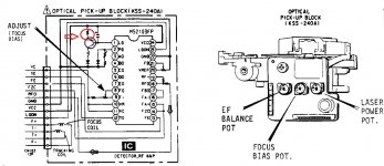
I checked the laser ,there was a small dark red light coming out.The laser is a KSS240A..someone must have messed with the 3 trimmers because there were some tiny pieces of broken plastic same as the trimmer.The laser power trimmer was fully turned in one position and the focus bias and tracking balance were almost at center position.i turned the laser power trimmer a bit to be almost at the middle and the focus trimmer a bit and it plays the cd now without issues,no whining,no strange noises.
I soldered some wires to test points of the pcb to perform future adjustments for focus ,eye patternt,tracking as described in the service manual when i have access to an oscilloscope.
But now how can i adjust the laser power trimmer to be on its original position? the label says 62.2ma.I guess i have to dissassemble the laser unit and solder some wires on this resistor to measure voltage drop while playing a CD...
Attachments
Last edited:
...or just be content that by setting the presets for best eye pattern and adjusting the power to give around 1.2v peak/peak signal it is going to be pretty much correct. Be sure to use a good commercial CD (clean and normal reflectivity) for adjustment and never use CDR or RW for alignment.
KSS-240A - different quality ?
This laser unit is available between arround € 5,00 - go to
KSS 240A KSS240A KSS 240 Radio CD Player Laser Linse Lasereinheit Optical Pick ups Bloc Optique|Autoradios| - AliExpress
and € 50 - go to
10X(KSS-240A KSS-240 KSS240A Radio Blu-Rays CD Player Objektiv Optische Ton 1Y8) | eBay
Are there experiences, where one get good quality ?
...or just be content that by setting the presets for best eye pattern and adjusting the power to give around 1.2v peak/peak signal it is going to be pretty much correct. Be sure to use a good commercial CD (clean and normal reflectivity) for adjustment and never use CDR or RW for alignment.
top article mooly,
full of super advice for not just sony units,thanks very much,
it just so happens i have a sony cdp-997 that might be similar,
there is nothing wrong with it but im thinking of gifting it to a old chap that wishes to have a reliable unit,
so if my track record is anything to go on ,its total recap time lol,
its fun!! and cheap compared to a night at the pub
")
but for my self i have just got another philips player,probably not worth the time ,i dont think its a good one like the philips cd204 ,i do know it has the lower end d/a converter being a single chip ,
the transport looks just ok ,
compared to the cdm-1 in the 204 and my cdp-302es which uses the bu-1 it does seem light weight ,
its a cd471 ,have you ever seen one before? i dont think they are very common here in nz
id love to see what you think of the model, it cost a huge $10 lol
any way have a super day and keep that soldering iron hot
mike
Can those cheap chinese oscilloscopes be used to show the eye pattern of a cdplayer and to calibrate it succesfully?
Hantek dso5102p usb digital storage oscilloscope 2channels 100mhz 1gsa/s Sale - Banggood.com
Hantek dso2d15 dual-channel + afg digital storage oscilloscope 150mhz 1gsa/s signal generator oscilloscope 2 in 1 Sale - Banggood.com
Hantek dso5102p usb digital storage oscilloscope 2channels 100mhz 1gsa/s Sale - Banggood.com
Hantek dso2d15 dual-channel + afg digital storage oscilloscope 150mhz 1gsa/s signal generator oscilloscope 2 in 1 Sale - Banggood.com
No idea tbh as I've never used one. The bandwidth is more than adequate but how a complex eye pattern would look I wouldn't like to say.
I imagine you would see some sampling artefacts and so it would look less clean than viewing on an analogue scope, but that it should be representative in amplitude given the bandwidth.
I imagine you would see some sampling artefacts and so it would look less clean than viewing on an analogue scope, but that it should be representative in amplitude given the bandwidth.
This laser unit is available between arround € 5,00 - go to
KSS 240A KSS240A KSS 240 Radio CD Player Laser Linse Lasereinheit Optical Pick ups Bloc Optique|Autoradios| - AliExpress
and € 50 - go to
10X(KSS-240A KSS-240 KSS240A Radio Blu-Rays CD Player Objektiv Optische Ton 1Y8) | eBay
Are there experiences, where one get good quality ?
Same thing, in second catalog is 10 pieces.
Good quality, i'm afraid not.
i was thinking of buying one of these but i cant find a video anywhere showing the eye pattern on such cheap oscilloscopes.I dont know whether they have this chop/alternative mode or not.
Chop and Alternate is used when using a scope in dual trace mode. Viewing the eye pattern is done with a single trace so those don't really figure into things.
Chop and Alternate is used when using a scope in dual trace mode. Viewing the eye pattern is done with a single trace so those don't really figure into things.
Looking at this service manual says to set input mode to alternate or chopper thats why i am asking.Havent done such a measurement before and i am a bit confused.
Attachments
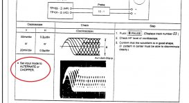
Well you would normally turn the second channel on the scope off (so it behaves as a single beam) and then the Chop/Alt don't apply. The eye pattern is a single measurement that can be done on a single beam scope.
------------------------------------
The difference if you have both traces running is that Alternate traces out first channel 1 and then channel 2 and so on. Chop displays both together with the traces literally 'chopped' as they scan left to right.
It makes a difference at really low sweep speeds where you want to see both traces together and not have one trace disappear while the other traces out.
Found this:
#31: Analog oscilloscope ALT, CHOP, ADD, INVERT vertical controls - YouTube
That's all it does
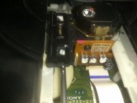
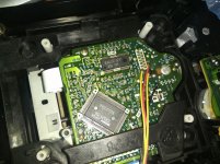
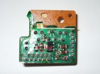
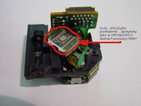
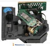
Today i received the kss240a i ordered 1 month ago for my denon-dcd625.The original kss240a loooks like the one below on the left but what i received had a 10pin ic instead of a 24pin and another extra ic that the original doesnt have.( picture on the right).When i bought it from the seller ,the photo corresponding to the item was that of the one with 24pins and so i decided to buy it but i received one with 10pin ic.
Is this of inferior quality?
Is this of inferior quality?
Attachments
As far as I know none of the replacements are genuine Sony parts and haven't been for nearly 20 years now.
All you can do is fit it and see how it performs. Its a totally different design electrically but as long as it works to the original spec then it should be OK.
Another difference you will notice is that original parts have the sintered phosphor bronze bearing shells whereas the replacements use moulded plastic.
- Home
- Source & Line
- Digital Source
- Sony CDP790 and KSS240 Restoration Project