It may be helpful for you to know that in the BC337/327 measurements I saw, the PNP has lower 1/F noise. I don't know what manufacturer it was though.
Here is some really excellent work on low noise BJT's.
Ultra low noise amplifiers
Object not found!
Ultra low noise amplifiers
More info on 337/327, slightly conflicting with above
http://www.janascard.cz/PDF/Design of ultra low noise amplifiers.pdf
As you can see, there are some super low noise, medium current BJT's but they do have quite a bit of capacitance.
cheers, T
Ah yes, yet another knucklehead who who never thought it was important to mention who the manufacturer was.
Different manufacturers can use entirely different processes for the same transistor, and in practice it seems to be the case that you cannot measure the Rbb of one transistor and expect it to apply for different manufacturers.
Recently I did verify roughly in RMS output noise measurement the Rbb of Fairchild factory (now Onsemi) BC550C, to be around 900 ohms. The Onsemi factory was the best AFAIK, and it seem like the OnSemi factory produces the SMD parts, but I don't know that for sure.
Also thinking about adding a small relay and a 82ohm resistor at the output to bring the gain down 20db, this of course also make the noise at the output very low
Is this the i/v resistor you are switching? In that case, the s/n ratio does not change.
Jan
Hello and thanks for your big effort, do the circuit work with a ES9018 Dac chip coupled for all 8 channels in parallel/ 16mA output?
Thanks
Hello,
no, it would have to be modified, I need the 8 individual channels of the es9018
Is this the i/v resistor you are switching? In that case, the s/n ratio does not change.
Jan
yes you're right of course, but I'm going to use the ES9018's digital volume, and since most of the time I listen to music at low volume, this switch is maybe useful.
Is this the i/v resistor you are switching? In that case, the s/n ratio does not change.
Jan
Yes it does - the amount varies.
There's a reason why big DR numbers on DAC data sheets are at large OP voltage swings. Double size of resistor = 1.414 x self noise.
Now, I know you will prolly point out that the self noise of the OP 'I-V' resistor is very small in the scheme of things -
it depends which DAC / OP current / size of resistor. When you get to crazy OP currents and DR numbers well over 130dB it can make a significant difference.
Just sayin'.
")
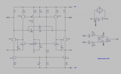
This week I've been thinking about alternatives to my I / V converter, because since I'm going to use 8 channels and balanced connections to the amplifier, that means I'll have to use 16 of these circuits.
A very interesting alternative is to use Jan Didden IV converter with a small change. just added a current source to increase the gain, the results are promising.
A very interesting alternative is to use Jan Didden IV converter with a small change. just added a current source to increase the gain, the results are promising.
Attachments
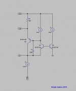
JD IV converter
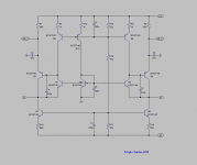
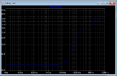
This is the Fully Differential IV converter, it has low input impedance with 0.2 ohms in the audio band and 2ohms at 1Mhz and 3 ohms at 10Mhz.
Distortion 10KHz at full output is also very low with only 3th harmonic as the differential nature of the circuit cancels even harmonics.
The PSRR is also good, but in reality will be worst than this depending on the tolerance of the components.
Attachments
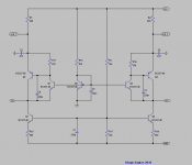
Even simpler, similar to Calvin's circuit in # 899
Nice one smms
What is the DAC OP Z and current swing for these results?
T
Indeed it's better suited for that as it has no thermal compensation.This could be used as the input of an MC phonostage.
Nice one smms
What is the DAC OP Z and current swing for these results?
T
It´s like the ES9018 at full output , I use a voltage source of 1.65Vdc /1.5Vac with 790 Ohms in series resistance
This could be used as the input of an MC phonostage.
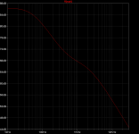
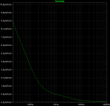
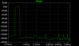
Here's what you asked for.
Attachments
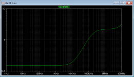
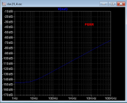
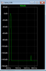
The calculated input noise with 5 ohms input is 0.36nV/Vhz
The gain at 1kHz is 68db but can be adjust changing R6 value.
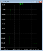
The distortion is with a 1mV 1KHz input signal ( 2.5 V output )
The gain at 1kHz is 68db but can be adjust changing R6 value.
The distortion is with a 1mV 1KHz input signal ( 2.5 V output )
Attachments
The biggest problem of the ztx 651...951/851 is the hfe...There are some zetex series that are never talked about which have much better hfe: ztc 1051a, 1055(npn), 1149(pnp).I have some and i'm using them especially in capacitor multipliers with fantastic results.You also find today the replacement of 2sa1038 and its complementary as smd...just google!
Look at Kenwood l-02a phono preamp schematic for the simplest thermal compensation!
Look at Kenwood l-02a phono preamp schematic for the simplest thermal compensation!
Last edited:
It´s like the ES9018 at full output , I use a voltage source of 1.65Vdc /1.5Vac with 790 Ohms in series resistance
Yes, goddit! I figured you were doing this.
Here's what you asked for.
WRT all these open loop / local FB / discrete designs, always good to start at 10 or 20kHz, as that is where they usually have problems with non linearities due to modulating capacitances.
But I've seen from your past work, you understand this well and have achieved excellent results.
T
- Status
- This old topic is closed. If you want to reopen this topic, contact a moderator using the "Report Post" button.
- Home
- Source & Line
- Digital Source
- dac I/V convertion with very low distortion