Could somebody tell a discrete op-amp that is fet input, very high slew rate,very high gain in open loop, unity gain stable , very low en noise and high output power? The only op-amp that i saw like this would be ths4631 .Do you know something even better in term of voltage noise but similar slew rate, current noise, etc...?
What's the noise of this circuit?
What circuit are you referring to?
Could somebody tell a discrete op-amp that is fet input, very high slew rate,very high gain in open loop, unity gain stable , very low en noise and high output power? The only op-amp that i saw like this would be ths4631 .Do you know something even better in term of voltage noise but similar slew rate, current noise, etc...?
Ths4631 seems to be a good opamp to use in an IV converter, but you will have to be very careful when drawing the printed circuit board to avoid parasitic oscillations because this amplifier is very fast
Audio opamp are not the better choice for a IV converter and one of the problems is the input impedance which is not constant and increases greatly with increasing frequency.
For example with an opa134 the impedance is only 0.002 ohms at 20hz and increase to almost 2 ohms at 20khz an increase of 1000 times, and then continues to increase being 6 ohms at 100kz and 110ohms
at 10mhz
For example with an opa134 the impedance is only 0.002 ohms at 20hz and increase to almost 2 ohms at 20khz an increase of 1000 times, and then continues to increase being 6 ohms at 100kz and 110ohms
at 10mhz
Attachments
this weekend I have been modifying my current conveyor to use a complementary compound input stage as Michael Smedegaard proposes on paper posted by jan.didden in # 880 and the input impedance is very low and constant, being 0.023 ohms at 20hz and only 0.026 at 20khz, at 100khz is only 0.079, and it only reaches 2ohms at 2Mhz, which opa134 had at only 20Khz.
I am designing this current conveyor to use with an ES9018, because I need 8 channels I ended up choosing this DAC, this week I hope to test the circuit in the breadboard, then post here if anyone is interested in seeing.
I am designing this current conveyor to use with an ES9018, because I need 8 channels I ended up choosing this DAC, this week I hope to test the circuit in the breadboard, then post here if anyone is interested in seeing.
Attachments
The one presented by Ian Didden, or yours...as it looks similar.do they show lower noise than the classical opamp in i/v? I want exceptionally high slew rates and exceptionally low noise too in such a circuit to make the i/v of some old pcm dac that deliver up to 1ma at full scale output.What circuit are you referring to?
Last edited:
I think it would be even better if that impedance would be 1 million times higher over 20khz...Audio opamp are not the better choice for a IV converter and one of the problems is the input impedance which is not constant and increases greatly with increasing frequency.
For example with an opa134 the impedance is only 0.002 ohms at 20hz and increase to almost 2 ohms at 20khz an increase of 1000 times, and then continues to increase being 6 ohms at 100kz and 110ohms
at 10mhz
I think that the op-amps are very good if their slew rate , noise and output power are adequate.I'm sure that a discrete circuit can be better, but i don't believe that any discrete circuit would be better than any op-amp.
Audio opamp are not the better choice for a IV converter and one of the problems is the input impedance which is not constant and increases greatly with increasing frequency.
For example with an opa134 the impedance is only 0.002 ohms at 20hz and increase to almost 2 ohms at 20khz an increase of 1000 times, and then continues to increase being 6 ohms at 100kz and 110ohms
at 10mhz
OPA134 is old and slow, though.
I don´t have nothing against op-amp or any other circuit that works with a global feedback loop (quite the opposite), but in this particular case of converting current to voltage, current conveyor have some advantages, they have ultra low noise , low and constant input impedance and are very fast, they can have more parts if you want more stability and better performance , but I use very inexpensive parts, all the parts for one of my current conveyor costs less than 1 euro.
@smms73: Hi ... with reference to your post #886:
.. I'd be interested in seeing what you may get to. I've tried simulating this circuit myself yesterday but couldn't get to very low distortion figures. Did you have any success?
Cheers,
Jesper
then post here if anyone is interested in seeing.
.. I'd be interested in seeing what you may get to. I've tried simulating this circuit myself yesterday but couldn't get to very low distortion figures. Did you have any success?
Cheers,
Jesper
No, I'd never seen that.
But he is using too much gain in the Sziklai pair, the circuit will have problems with parasitic oscillations.
No, it doesn't. It's the cleanest measuring and sounding circuit ever, and fully understanding is beyond most diy-ers, me included.
Still, it would be nice for someone to build it.
Jan
Hi,
Smeedegards paper triggered me years ago to look into CFP circuits.
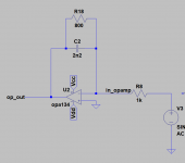
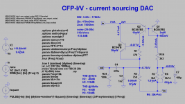
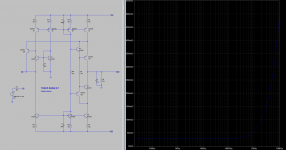
Here´s a sim I did in 2016 of a CFP-I/V, almost as simple as it could get, even requiring only a single negative supply rail.
It is intended for current sourcing DACs like PCM1794, or PCM1795 in Mono mode.
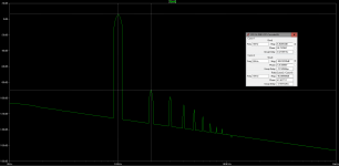
THD is simmed at 10kHz and fullscale (2.1Vrms, H2@-96dB).
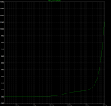
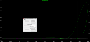
Zin remains at ~500mOhm up to to 5.7MHz, doubling at ~17MHz.
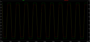
Noise simmed at -125dBV .... 10k-square looks clean.
Heat power losses are soo low, that one doesn´t need to worry about addiotional cooling.
Q1, Q2 are dual matched BC-trannies for tight thermal coupling, easy to source ...costing only a few pennies.
If one wants to omit with the output coupling cap, just replace R3/C3/C4 by a first current mirror with a CCS-load (could be another, second, dc-servoed CM that nulls the CM´s idle current) and connect R3/C3 from the first CM´s output leg to gnd.
Only drawback of this circuit is the almost missing PSRR, so that a perfectly clean supply is a prime requirement.
The CM-modification -the more so with the second CM and dc-servo option- is much better in this regard, as the CMs shield against the supply rails and also references the I/V-conversion impedance and the dc-servo to gnd.
But best of all .... these simple circuits let music come through.")
jauu
Calvin
Smeedegards paper triggered me years ago to look into CFP circuits.
Here´s a sim I did in 2016 of a CFP-I/V, almost as simple as it could get, even requiring only a single negative supply rail.
It is intended for current sourcing DACs like PCM1794, or PCM1795 in Mono mode.
THD is simmed at 10kHz and fullscale (2.1Vrms, H2@-96dB).
Zin remains at ~500mOhm up to to 5.7MHz, doubling at ~17MHz.
Noise simmed at -125dBV .... 10k-square looks clean.
Heat power losses are soo low, that one doesn´t need to worry about addiotional cooling.
Q1, Q2 are dual matched BC-trannies for tight thermal coupling, easy to source ...costing only a few pennies.
If one wants to omit with the output coupling cap, just replace R3/C3/C4 by a first current mirror with a CCS-load (could be another, second, dc-servoed CM that nulls the CM´s idle current) and connect R3/C3 from the first CM´s output leg to gnd.
Only drawback of this circuit is the almost missing PSRR, so that a perfectly clean supply is a prime requirement.
The CM-modification -the more so with the second CM and dc-servo option- is much better in this regard, as the CMs shield against the supply rails and also references the I/V-conversion impedance and the dc-servo to gnd.
But best of all .... these simple circuits let music come through.
jauu
Calvin
Attachments
Last edited:
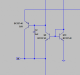
the simulation with bc857/847 that Calvin uses has no problems with parasitic oscillations , but with the bc327/337 I have problems with oscillations
I will build in a breadboard a circuit to test the stability of the complementary compound pair with various types of transistors.
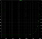
simulating the Smeedegards complementary compound pair input in my circuit using the bc857/847 gives a input impedance of only 0.03ohms all the way to 100khz, 0.06ohms at 1Mhz and 0.5ohms at 10Mhz
The distortion is also very low 0.0005% with a 780 ohms DAC (es9018)
I will build in a breadboard a circuit to test the stability of the complementary compound pair with various types of transistors.
simulating the Smeedegards complementary compound pair input in my circuit using the bc857/847 gives a input impedance of only 0.03ohms all the way to 100khz, 0.06ohms at 1Mhz and 0.5ohms at 10Mhz
The distortion is also very low 0.0005% with a 780 ohms DAC (es9018)
Attachments
- Status
- This old topic is closed. If you want to reopen this topic, contact a moderator using the "Report Post" button.
- Home
- Source & Line
- Digital Source
- dac I/V convertion with very low distortion