") of course it's too hard to replace r5 with a lower noise current source, but yes, you're right...i'm not an expert in anything...that is why i will stick with the op-amps psrr...No matter what you do, in the end you get the average thd+N when using discretes just because of the size of the circuit.I know that bc337/327 models are easily calculated by LtSpice, but using other transistor models in an i/v circuit of my own wasn't even possible to be modeled which makes me think that actually the bc337 model give ideal figures, not real ones.Did you measured those circuits in real life? Some of your circuits look like the discrete incarnation of AD844 to me and there were guys who are using the AD844 for a decade now...
of course it's too hard to replace r5 with a lower noise current source, but yes, you're right...i'm not an expert in anything...that is why i will stick with the op-amps psrr...No matter what you do, in the end you get the average thd+N when using discretes just because of the size of the circuit.I know that bc337/327 models are easily calculated by LtSpice, but using other transistor models in an i/v circuit of my own wasn't even possible to be modeled which makes me think that actually the bc337 model give ideal figures, not real ones.Did you measured those circuits in real life? Some of your circuits look like the discrete incarnation of AD844 to me and there were guys who are using the AD844 for a decade now...
Last edited:
for some songs you might need 50db THD to make them listenable.Let me do those circuits, i have the left backgroundThis is the circuit I use to listen to the discs of Tori Amos, it has the necessary distortion -89db
which TI app circuit?This is a long and old thread, have either of you used the TI application circuit? I was told by someone that the opamps just cook, so I suggested to parallel a couple instead.
This is a long and old thread, have either of you used the TI application circuit? I was told by someone that the opamps just cook, so I suggested to parallel a couple instead.
Better with buffer´s
edit: Use audio op-amp´s not lt1007 , of course
Attachments
Last edited:
Bc327/337 gives realistic results almost every time, in real circuit normally you get less distortion than in simulation because the early effect is worst in simulation models than in reality. Yes I have already build and measure some of this circuits, and yes they have very low distortion, I have post some of my measurements in the forum but it was years ago as I stopped posting on the forum around 2014
edit: you can see some measurements here:
dac I/V convertion with very low distortion
Last edited:
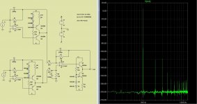
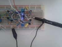
This was the circuit I used back in 2012 to test the distortion of the circuit
5% carbon resistors and random transistors .
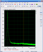
this test was made with 8ma at the input and 4volts output, two times more current that a pcm1794 could provide at the output, as you can see the distortion is immeasurable.
The distortion was measure with a emu1212 using the Arta program.
5% carbon resistors and random transistors .
this test was made with 8ma at the input and 4volts output, two times more current that a pcm1794 could provide at the output, as you can see the distortion is immeasurable.
The distortion was measure with a emu1212 using the Arta program.
Attachments
because It Is user friendly and with lowest jitter <50 psec
please take a look AK4118 Digital Receiver Board Coaxial Optical AES to I2S Sampling Rate Display | eBay
you got select from 3 spdif and I2S Input, display
you can think to do a modular type pcb - separate pcb for pcm1794 with I2S Input, separate pcb for analogue I/V, separate power supply pcbs
BTW would anyone please confirm connecting of DC servo schematic that Sergio proposed https://www.diyaudio.com/forums/dig...convertion-low-distortion-43.html#post5730676 to last Tagus differential https://www.diyaudio.com/forums/dig...convertion-low-distortion-43.html#post5728559 and Tagus X https://www.diyaudio.com/forums/dig...convertion-low-distortion-42.html#post5727102 schematics
why? experience? it does look like it is a good part to use, 0.5mm pitch soldering can be an issue for some.
Last edited:
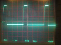
Thank you! I never tried to use a sound card for measuring distortions as i had some doubts upon the truth it can provide.I saw once a 1000w /2 ohms audio amplifier measured under ARTA and the results were smth like 0.00006% at 150w/8ohm which automatically triggered an alarm for me.I think that it's absolutely impossible to get those results in real life and i don't believe anyone in the world that they can get you such results with a high power amplifier .To be absolutely honest i appreciate more a simple sine-square signal measurement on a scope . It would be nice if the audio manufacturers would provide ultralow distortion equipment and a separate distortion" eq" box to give you the option of making the music sound "worse".This was the circuit I used back in 2012 to test the distortion of the circuit
5% carbon resistors and random transistors .
this test was made with 8ma at the input and 4volts output, two times more current that a pcm1794 could provide at the output, as you can see the distortion is immeasurable.
The distortion was measure with a emu1212 using the Arta program.
I saw once a 1000w /2 ohms audio amplifier measured under ARTA and the results were smth like 0.00006% at 150w/8ohm which automatically triggered an alarm for me.
What kind sound card to measure? There is any sound card that can loop back with 0.00006% THD?
You got the pointWhat kind sound card to measure? There is any sound card that can loop back with 0.00006% THD?
Unfortunately not many are aware of the fact that it is physically impossible to get those measurements with just a sound card...you don't pay 6000-20000 dollars for just a "20 kilos empty box"called THD analyzer...Some say that you can do it with a fairly good soundcard if you attach a distortion lens magnifier and a high quality notch filter though...I never tried.I might try it soon because i don't have 6000 dollars to spend for anything in this world
Last edited:
You got the point
BS.
Bob Cordell distortion magnifier can do magnify 40dB Linear Audio | your tech audio resource
To get amplifier 0.00006% THD is very difficult.
I used Distortion Analyzer in my previous work, long time ago.
Hi Serjio,
Would you please confirm, when we want to use schematic with dac chips without offset, like pcm1704, we don't use Q7.
If we like to go without coupling caps dc servo dac I/V convertion with very low distortion can be added to the output, but would you please explain how to connect It.
Would you please confirm, when we want to use schematic with dac chips without offset, like pcm1704, we don't use Q7.
If we like to go without coupling caps dc servo dac I/V convertion with very low distortion can be added to the output, but would you please explain how to connect It.
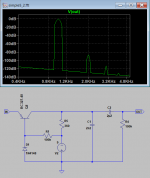
A forum member asked me to make a functional circuit for the pcm1794a, and this weekend I was in ltspice and did this, the idea was to have a more stable circuit. The resistance R3 can be a resistance of 180ohm in series with a potentiometer of 100 ohms, this will serve to cancel the DC offset at output, (R11,12,16,17) can have a lower value , with 10 Ohms value the input impedance is 7 ohms. Vcc is 15V and Vdd is -15V.
Yes, for Dac´s without current offset you don´t use Q7, if you don´t want to use a capacitor at the output you can use the circuit in #854 , you only need to connect to the output of the I/V converter , that circuit will sence the DC voltage at the output and will keep the output always at zero.
But you can also use a Polyphenylene Sulfide Film Capacitor (PPS) at the output, they are completely transparent and produce no distortion, they are a bit expensive but for me they are the best choice, in my view a good PPS capacitor like the SMR series from Kemet is preferable than using a dc servo based on an opamp.
https://pt.mouser.com/datasheet/2/212/KEM_F3072_SMR-1103375.pdf
- Status
- This old topic is closed. If you want to reopen this topic, contact a moderator using the "Report Post" button.
- Home
- Source & Line
- Digital Source
- dac I/V convertion with very low distortion