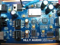
The AMS117 is one 3.3V regulator and LM317 probably was the second 3.3V one (separate powers?).
Supply comes from the jack in right (next to big capacitors and LED). I really doubt that is anything to gain from modding the power supply on a digital-only board.
A lot of improvement gained by using a good psu for dac, so what's your explanation behind you view here? Care to share..
Hi
Thanks for the reply.
The unit be powered by USB or external dc of 8 to 12 V.
The 3.3 V line is derived from the LM 317 and it has been replaced.
The TCXO works on 5V and I am trying to replace it.
thanks
kp93300
Why don't power directly the TXCO? when I powered the BII clock with Salas BiB I heard a big improvement so let's go
")
A lot of improvement gained by using a good psu for dac, so what's your explanation behind you view here? Care to share..
My explanation is that this is not a DAC. It is just a digital converter and since no analog signals are generated, there is not too much to gain in a super clean power supply in the low frequency domain (below 100kHz, like the DAC needs).
At the frequencies involved (12 MHz) and fast slew rates of digital fronts (equivalent of hundreds of MHz), the inductances of the traces between the power supply and consumers (digital cips) basically isolates those two in AC domain. Any "improvement" done in the power supply's HF response will not translate in better voltage for the digital chip (in the frequency range that is relevant here). In DC domain the digial cips are happy even with +/- 10% variation, so is nothing to gain there either.
Actually, that is the reason why not a single comercial regulator that can operate well over 1MHz. Because... is no need of that, the traces will cancel all that "performance".
Because of the high frequancy local capacitors are 100 times more important than the power regulator in digital domain, and that board seems to have very good local decoupling - solid tanatalum with ceramics on every cip supply.
Sure, people claim "big improvements" but none backs that with a real measurements (like the cristal jitter). Actuall those improvements are because the cristal does not inject as much RF in the analog portion of the DAC, not because the new PS somehow did something usefull for the cristal. Nobody showed mesurements to prove improvement of jitter because of a fancy PS (as opposed to just a regular decent IC one).
Last edited:
Why don't power directly the TXCO? when I powered the BII clock with Salas BiB I heard a big improvement so let's go
Hi Merlin,
This is what i intend to do and looking for ideas to do it neatly. i wish to place the clock as close as possible to the board.
There is a constant noise heard through the speaker and coming from the HLLY board.
I hope the new power supply can solve the problem.
Otherwise the SQ is very good .
The 3.3 V is a diy version of the BIB salas shunt and is off board. Nice improvement.
regards
kp93300
Hi Korben
Answer in red:
Cheers
Felipe
Answer in red:
Hi Merlin,
This is what i intend to do and looking for ideas to do it neatly you need to know wich pin in txco is the 5V and after follow the trace to see where is coming the 5V, after you only needs to cut the trace or take off a component to disconnect the 5V supplied by the pcb & connect the new 5V regulated at the txco pin. i wish to place the clock as close as possible to the board I don't understand you, do you want to take off the clock of the pcb?.
There is a constant noise heard through the speaker and coming from the HLLY board are you sure is all well grounded.
I hope the new power supply can solve the problem.
Otherwise the SQ is very good what's SQ?.
The 3.3 V is a diy version of the BIB salas shunt and is off board. Nice improvement.
regards
kp93300
Cheers
Felipe
Definitely you have grounding issues. Messing with the regulators won't solve that.
You need an USB cable with all four wires, even if you use separated PS, just to connect the grounds (PC with receiver).
Use coax cable on SPDIF or shielded CAT5 if you use I2S (use the shield to connect grounds). You could also try normal CAT5E with one grounding wire taped close on it's surface.
You need an USB cable with all four wires, even if you use separated PS, just to connect the grounds (PC with receiver).
Use coax cable on SPDIF or shielded CAT5 if you use I2S (use the shield to connect grounds). You could also try normal CAT5E with one grounding wire taped close on it's surface.
- Status
- This old topic is closed. If you want to reopen this topic, contact a moderator using the "Report Post" button.
- Home
- Source & Line
- Digital Source
- HLLY USB SPDIF/ I2S CONVERTER