Hi ashok,
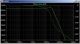
Your circuit simulates great. The really interesting thing is that frequency response varies very little with load. I wonder if you can point me to some resources / what equations you need to design these types of filter.
The simulations continue.... will post final schematic when completed.
Your circuit simulates great. The really interesting thing is that frequency response varies very little with load. I wonder if you can point me to some resources / what equations you need to design these types of filter.
The simulations continue.... will post final schematic when completed.
Must modify my present filter.
Hi Zodiac.
I used free software (DOS) from the web for designing the filter. I am still searching for the downloaded copy. I could not find it on the net now. If I find it I will let you know.
I think I must also include the peak at 20KHz as I get some droop as it reaches 20 KHz. A P3A DAC was flat up to 20KHz.
I will also have to make an air core inductor and see how it compares with what I have.
Cheers.
It's an old thread I know and hopefully someone could give me a tip.
I tried to build a low pass filter in my tda1541a dac but the only result I get is the right channel gives a big hum and some bzz. The left channel is ok about the hum but also a bzz but less then the right channel.
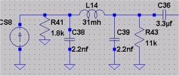
Attached an example of a tda1541a filter I tried, I nly use ecc88 tubes as output.
Already checked all connections, soldering and so on. Th dac is functioning perfect without filter. Still I want to try a filter.
Thanks,
Ad.
I tried to build a low pass filter in my tda1541a dac but the only result I get is the right channel gives a big hum and some bzz. The left channel is ok about the hum but also a bzz but less then the right channel.
Attached an example of a tda1541a filter I tried, I nly use ecc88 tubes as output.
Already checked all connections, soldering and so on. Th dac is functioning perfect without filter. Still I want to try a filter.
Thanks,
Ad.
Attachments
There's an online LC filter designer here : RF Tools | LC Filter Design Tool
The filter shown in your schematic has two inductors so to design something similar set the filter type to 'Lowpass Chebyshev' with 'Shunt first' and 5th order. Set the cutoff frequency to somewhere close to 20kHz. The input impedance is 4500 ohm and the output impedance 27000 ohm. Passband ripple I usually set to 0.3 - 0.5dB.
The filter shown in your schematic has two inductors so to design something similar set the filter type to 'Lowpass Chebyshev' with 'Shunt first' and 5th order. Set the cutoff frequency to somewhere close to 20kHz. The input impedance is 4500 ohm and the output impedance 27000 ohm. Passband ripple I usually set to 0.3 - 0.5dB.
- Home
- Source & Line
- Digital Source
- Low pass filter design for TDA1541