Hello Mayday!
Good to see your experiment with your player.
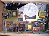
I have a cd-40 that modified a half year ago. It's just sound incredible good.
Now I listen with an Infinity Qa speaker with EMIT tweeter, just superb detailed and transparent with a lots of air.
Super in every way.
Never go back for normal speaker that for sure.
I read ecdesign's treat all over and tried some of his circuit.
You should try the reg for the 1541 its cheap to build and worth a lot!! clean power very important!
there is an easy way of DEM sync with the WS signal. used with the I2S attenuator.
The wima caps not the best solution and after the I2S att. is not needed at all.
Here is a part from the DEM clock from ecdeign:
"The DEM clock needs to have low jitter and induce lowest possible crosstalk. The problem is that the DEM clock needs to be injected in an on-chip oscillator that must not be allowed to oscillate.
The DEM clock has direct effect on the bit errors of the 6 MSBs in the TDA1541A, and on-chip crosstalk (inter modulation between DEM clock and other on-chip clocks) thats why there are clearly audible differences between DEM clock circuits.
I noticed that the indicated 200KHz DEM clock causes a number of issues like problems with active divider settling time, crosstalk with on-chip clock signals, ground-bounce, and problems with external decoupling film caps (inductance).
Other problems are the extra divider and inverter required to derive the DEM clocks that add jitter (every logic element adds jitter). The DEM clock distribution among multiple TDA1541A chips is also problematic.
So I tried to design a simple but highly effective DEM clock injection circuit that uses one of the local I2S signals.
After some experimenting I decided to use the WS signal (44.1 KHz). Decoupling cap value can be increased to approx. 400nF (390nF) in order to achieve similar filter characteristics although 100nF worked fine too.
WS was connected to the anode of a Schottky diode, the cathode was connected to a resistor of exactly 13K, and the resistor was connected to pin 16. Pin 17 was left unconnected.
The value of 13K corresponds with a WS signal amplitude of exactly 3.3V (SD-transport I2S output level). The value needs to be increased to 14 ... 15K when when using 5V signal level. The value of the resistor is critical, too high tolerance will prevent the on-chip DEM clock from tracking. This method uses current steering, so the current deviations must be tuned in such way that the DEM oscillator tracks reliably."
I hope you find it useful. I know its a long way to achieve our goal.
Your board looks similar to me
")
I haven't tried the shunt regs yet - too busy listening to it ;o) I was considering having a go with the TL431's as per TNT Audio but work keeps getting in the way of all my fun!
How hot does that regulator get? Too hot for 'hot melt glue'?
I don't know yet, but I guess it runs rather hot. UV101 and Andrew recommended large heatsink for it.
It does indeed get hot but I'm suggesting keeping you're existing PSU and heatsink (altered to supply 7v) then regulating again, locally, down to the 5v required by the 7220. I don't know if the local regulator would still need a heatsink as I've only tried this on the 1541. It would help, of course, if I really understood these things!
It does indeed get hot but I'm suggesting keeping you're existing PSU and heatsink (altered to supply 7v) then regulating again, locally, down to the 5v required by the 7220. I don't know if the local regulator would still need a heatsink as I've only tried this on the 1541. It would help, of course, if I really understood these things!
I don't think it matters that much if I take Vin to the 7805 from Vin from the original 7805 or from Vout from a 7807. I'm thinking it's the almost 200mA that makes the reg for the SAA7220 hot. Just what I think...not gospel.
I'm thinking I can fixate the regs with non-conductive silicone. The type used as a sealant(spelling)? In engines. I should have some at home.
It hardens to a firm rubbery consistence. I could also use this to fixate the SAA7220 reg on the pcb by laying it on it's back, heatsink down. There's plenty of empty space near the SAA7220 to do this.

Nice work Goran!
Very extensive modification by the looks of it
Thanks
It was really fun to make all those mods and it was worth. Doesnt look nice but sounds really good.
Does somebody by have a picture of the bottom side of the CD40 with the PCB removed?
I have left over a light gray plastic rocker-like part of about 10cm length which I did not disassemble but it fell of the case somehow (to my big surprise!). I guess it belongs to the drawer mechanism but can't figure out how. I can find it in the service manual (part 253) but this does not help.
Thanks in advance.
An externally hosted image should be here but it was not working when we last tested it.
Schematic is designed by R. Meijer, not mine. But sounds good.
hi.. been reading this thread as I'm modding my own CD50. Can anyone confirm if the above mentioned regulator actually works? I tried to build it but I'm not getting more that +/- 2,3 volts. I double and triple checked all my connections on separate days and as far as I can tell I dont see any mistakes on my part.
Probably the mistake is mine..but if someone can give me a heads up that the schematic and suggested values actually work that would be great.
Did you ever finish this mod? I found the instructs from lampiztor a bit vague, and would like to do the same on my philips 740.... would love to see some photos too if possible! cheers, rod
There are 100's of pictures here. You could always just read the thread????
Hi,
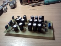
I just want to share some pictures of my CD50 with some modifications based on this thread.
I have to say that the results so far are wonderfull.
For now I made several regulators, one for each voltage supply on each chip, new capacitors, Panasonic on the PS and Nichicon elsewhere. New PS diodes, new opamps and Mundorf caps between the opamps and the new RCA's.
I still have to do the dac's caps and install a new clock.
The regulators where mounted on heatsinks removed from an old PC power supply.
Here are some pics.
Thank you all for all the information and inspiration. You are great
Ricado
I just want to share some pictures of my CD50 with some modifications based on this thread.
I have to say that the results so far are wonderfull.
For now I made several regulators, one for each voltage supply on each chip, new capacitors, Panasonic on the PS and Nichicon elsewhere. New PS diodes, new opamps and Mundorf caps between the opamps and the new RCA's.
I still have to do the dac's caps and install a new clock.
The regulators where mounted on heatsinks removed from an old PC power supply.
Here are some pics.
An externally hosted image should be here but it was not working when we last tested it.
An externally hosted image should be here but it was not working when we last tested it.
An externally hosted image should be here but it was not working when we last tested it.
An externally hosted image should be here but it was not working when we last tested it.
An externally hosted image should be here but it was not working when we last tested it.
Thank you all for all the information and inspiration. You are great
Ricado
That should be starting to sound nice
What's next on the list? Clock??
If you want to clock, you should get something capable of outputting /2 and /4 clock speeds. You should clock the decoder and filter direct with the main clock and then the /2 for the tda. The /4 gives you the option of running active DEM clocking.
Here's a document the document I wrote about clocking. It also contains lots of other info gathered from other threads on here.
http://www.fidelityaudio.co.uk/1541 clocking_03.2ver.pdf
Hi Ricardo:
Congratulations for your work. Modified TDA1541A CD players are really nice sounding machines! Hard to beat must I say!
Continue your work, take off the op-amps and jump to a discrete output stage or tubes (remember there is no op-amp like no op-amp).
A new clock (with own power supply) it is a must also!
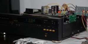
Attached are a pic about my Marantz CD50SE, not finished yet!
All the best to DIYAUDIO community,
Antonio
Congratulations for your work. Modified TDA1541A CD players are really nice sounding machines! Hard to beat must I say!
Continue your work, take off the op-amps and jump to a discrete output stage or tubes (remember there is no op-amp like no op-amp).
A new clock (with own power supply) it is a must also!
Attached are a pic about my Marantz CD50SE, not finished yet!
All the best to DIYAUDIO community,
Antonio
Attachments
- Status
- This old topic is closed. If you want to reopen this topic, contact a moderator using the "Report Post" button.
- Home
- Source & Line
- Digital Source
- Marantz CD-50 and CD-60, TDA1541, CDM4/19