no, put the resitor on the horizontal line after the LED's then the 100nf cap to shunt the noise to gnd asper the 1st diagram")
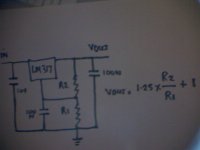
Trying my best to get what you mean...any closer?
or:
Last edited:
Hi
A LM317 can be used in many ways, however coupling LED's is guaranteed to introduce noise, to a required output. ( unless you use a Infra Red LED biased at 20ma ,which is not appropriate in a LM317 regulator ).
In the schematic just posted the Adjustment pin is not configured correctly as R2 and R1 are in series - adding resistance, rather it is trying preference to bias the LED, and forgetting to apply current to the LM317 correctly.
A LM7805 is a neat simple alternative to deliver 5v, but if your application requires a LM317 read on.
To get 5v out you just need 2 resistors, they have a defined relationship with the adjustment pin that outputs. 1.25 volts, and the output that is a resistance divider with a reference of 1.25v midway. You can see the LM317 is a versatile regulator, allowing a maximum of up to 37v between its input and output.
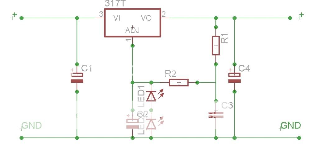
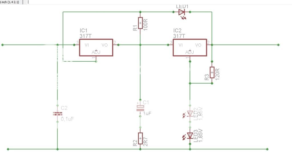
So in our circuit below grab a calculator and follow, 510/160 x1.25+1 = 4.98 ( a more convenient rewrite of the formula ) if R2 in the attached schematic is 160 ohms ( and it can be as low as 120 ohms, which is convenient to match resistors to R1 for different voltages ) we then make R1 510 ohms this then provides 4.98 v, or if we make R1 adjustable using a 1k trim
you can achieve exactly 5v over different ranges of R2 - however no lower than 120 ohms.
Here is a application note for the LM317 http://www.national.com/mpf/LM/LM317.html#Overview
The capacitors should be rated at over the desired voltage by factor of 2, remembering Vin may be higher than Vout, it is good to allow the LM317 a bit of Vin headroom ie it must be at least 3v higher than Vout. ( 5v is easier to remember ) ie if Vout is 5v then Vin should be at least 8v preferably 10v. Make Vin 1uf , Cap from adj to gnd 100 nanofarad ( 104 ) and Vout 100n (104 ) If you load too much capacitance, you then require diodes to protect the regulator from the adjustment cap discharging.... which makes the circuit more complicated.
Hope this helps Cheers / Chris
A LM317 can be used in many ways, however coupling LED's is guaranteed to introduce noise, to a required output. ( unless you use a Infra Red LED biased at 20ma ,which is not appropriate in a LM317 regulator ).
In the schematic just posted the Adjustment pin is not configured correctly as R2 and R1 are in series - adding resistance,
rather it is trying preference to bias the LED, and forgetting to apply current to the LM317 correctly. A LM7805 is a neat simple alternative to deliver 5v, but if your application requires a LM317 read on.
To get 5v out you just need 2 resistors, they have a defined relationship with the adjustment pin that outputs. 1.25 volts, and the output that is a resistance divider with a reference of 1.25v midway. You can see the LM317 is a versatile regulator, allowing a maximum of up to 37v between its input and output.
So in our circuit below grab a calculator and follow, 510/160 x1.25+1 = 4.98 ( a more convenient rewrite of the formula ) if R2 in the attached schematic is 160 ohms ( and it can be as low as 120 ohms, which is convenient to match resistors to R1 for different voltages ) we then make R1 510 ohms this then provides 4.98 v, or if we make R1 adjustable using a 1k trim
you can achieve exactly 5v over different ranges of R2 - however no lower than 120 ohms.
Here is a application note for the LM317 http://www.national.com/mpf/LM/LM317.html#Overview
The capacitors should be rated at over the desired voltage by factor of 2, remembering Vin may be higher than Vout, it is good to allow the LM317 a bit of Vin headroom ie it must be at least 3v higher than Vout. ( 5v is easier to remember ) ie if Vout is 5v then Vin should be at least 8v preferably 10v. Make Vin 1uf , Cap from adj to gnd 100 nanofarad ( 104 ) and Vout 100n (104 ) If you load too much capacitance, you then require diodes to protect the regulator from the adjustment cap discharging.... which makes the circuit more complicated.
Hope this helps Cheers / Chris
Attachments
Last edited:
Hi
A LM317 can be used in many ways, however coupling LED's is guaranteed to introduce noise, to a required output. ( unless you use a Infra Red LED biased at 20ma ,which is not appropriate in a LM317 regulator ).
I'm fairly certain that LED's are used in many circuits for the exact purpose proposed here?? The original circuit was taken from a post on PFM.
In the schematic just posted the Adjustment pin is not configured correctly as R2 and R1 are in series - adding resistance,
Not following that at all
I'd say the adj pin was configured to function exactly as intended. The only components involved in setting the output voltage are the LED's in this circuit. The remaining 1.25v is the difference between the adj and out pins.R2 does not form part of the circuit involved in setting the output voltage. The voltage either side of R2 will be approximately the same. R2 in my original drawing was only 10r & together with C2 (100n) it is a filter (admittedly a finger in the air approach without calculation). I very much doubt it would effect output voltage.
A LM7805 is a neat simple alternative to deliver 5v, but if your application requires a LM317 read on.
The idea is to get to something better than a 7805 at very low cost!
To get 5v out you just need 2 resistors, they have a defined relationship with the adjustment pin that outputs. 1.25 volts, and the output that is a resistance divider with a reference of 1.25v midway. You can see the LM317 is a versatile regulator, allowing a maximum of up to 37v between its input and output.
So in our circuit below grab a calculator and follow, 510/160 x1.25+1 = 4.98 ( a more convenient rewrite of the formula ) if R2 in the attached schematic is 160 ohms ( and it can be as low as 120 ohms, which is convenient to match resistors to R1 for different voltages ) we then make R1 510 ohms this then provides 4.98 v, or if we make R1 adjustable using a 1k trim
you can achieve exactly 5v over different ranges of R2 - however no lower than 120 ohms.
Here is a application note for the LM317 LM317 - 3-Terminal Adjustable Regulator
The capacitors should be rated at over the desired voltage by factor of 2, remembering Vin may be higher than Vout, it is good to allow the LM317 a bit of Vin headroom ie it must be at least 3v higher than Vout. ( 5v is easier to remember ) ie if Vout is 5v then Vin should be at least 8v preferably 10v. Make Vin 1uf , Cap from adj to gnd 100 nanofarad ( 104 ) and Vout 100n (104 ) If you load too much capacitance, you then require diodes to protect the regulator from the adjustment cap discharging.... which makes the circuit more complicated.
Hope this helps Cheers / Chris
Ok so there is the data sheet theory from the start of the discussion, how to use the formula to set the voltage as per the data sheet. The idea here is to try something that may be slightly better if not different and teach something along the way. (at worse, explain how the regulator works)
Why do the caps need to be rated at twice the voltage?
I understand the possible requiredment for the protection diode, but as we are not talking about lots of uF post reg and a load will quickly discharge any caps after the reg, I've not included it.
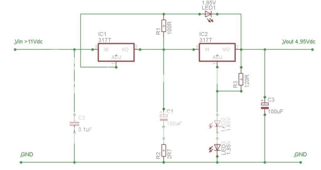
So, UV101, other then C2 being 0,1uF and R2 being 10R and R1 240R and I'll use one 3,6V LED...what values would use for the rest?
As for the discussion above, I'm not qualified to even have an opinion.
The point however is to create a regulator with as low noise as possible to a reasonable price and that's not too difficult to put together.
As for the discussion above, I'm not qualified to even have an opinion.
The point however is to create a regulator with as low noise as possible to a reasonable price and that's not too difficult to put together.
Hi
For a good appreciation See the attached tutorial on LM317 setting its output voltage:
http://diyaudioprojects.com/Technical/Voltage-Regulator/
and I apologize R1 and R2 were labelled wrongly in my schematic, ( too many late nights recently ) they needed to be reversed, however their meaning is expressed correctly to have the lower resistor divided by the adjustment resistor to obtain a higher figure.
The noise of LED's that depends on their bias has been provided in DIY Audio - thanks to the tremendous work of member Christer see:
http://www.diyaudio.com/forums/part...surements-leds-zener-diodes-7.html#post417008
So what do we determine ? is that introducing an LED to an LM317 circuit, is to introduce a source of noise, If a LED must ( and best if it is left out for audio purposes ) be used for illumination of ON status, its best location is prior to the LM 317 with a suitable bias resistor
Cheers / Chris
Last edited:
I completely disagree about LED noise being worse than using the std voltage divider approach.
I many circuits, an LED is used as a low noise voltage reference.
Accoustica LM317
Accoustica LM317 TPR
http://www.diyaudio.com/forums/power-supplies/134801-simplistic-mosfet-hv-shunt-regs.html
http://www.diyaudio.com/forums/power-supplies/143693-simplistic-salas-low-voltage-shunt-regulator.html
Admittedly, if I could obtain something like an LM4040 set at approx 3.75v this would be preferable.
I repeat that the aim here is not to design the "definitive" regulator. It’s to build something better than a 7805, better than the std datasheet LM317 and keep costs absolutely minimal, and use it to improve the power supplies of the CD in this thread.
One comment I am interested to understand, is that the caps should be rated at twice the rail voltage. Are you able to clarify?
Last edited:
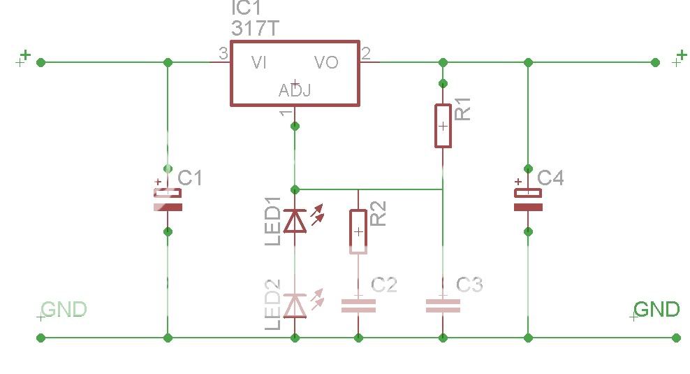
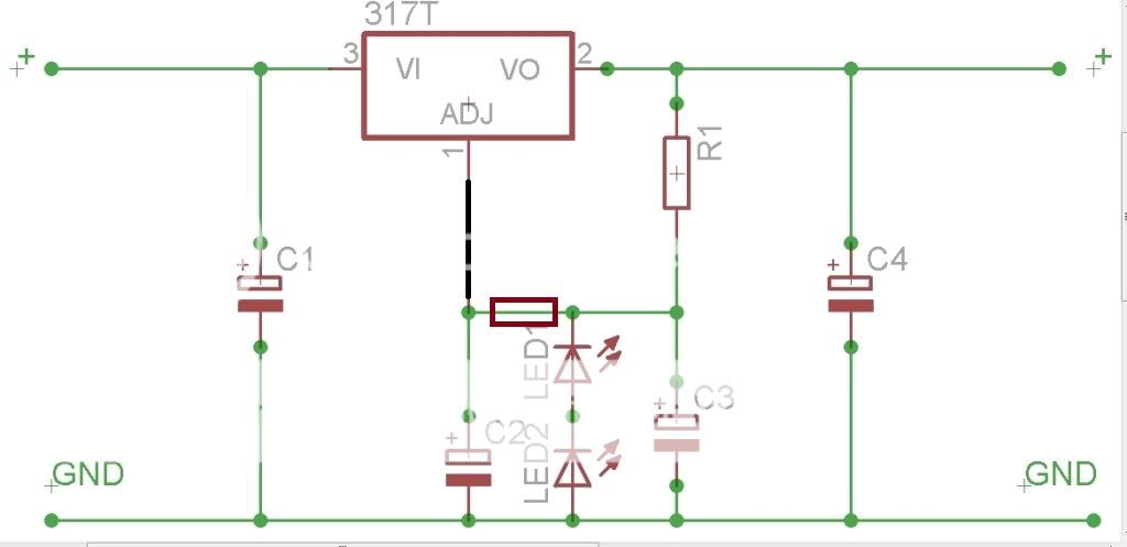
I'm considering this design now, although I am uncertain about the values of LED1, R1 and R2, and also if there should be a cap across output(value/type?)
A helpfull member on a swedish forum helped me with this, fired of a few more question, including the ones above but he hasn't had the time to answer yet.
EDIT: didn't know how to "flip" the first LM317 upside down in eagle as per the original TPR schematic...
Thoughts?
A helpfull member on a swedish forum helped me with this, fired of a few more question, including the ones above but he hasn't had the time to answer yet.
EDIT: didn't know how to "flip" the first LM317 upside down in eagle as per the original TPR schematic...
Thoughts?
Last edited:
Thoughts?
Keep it simple to start. You need to learn to walk before you can run!
Read the Accoustica TPR stuff I link to earlier this morning.

Keep it simple to start. You need to learn to walk before you can run!
Read the Accoustica TPR stuff I link to earlier this morning.
I have those pages bookmarked. Been a week or more since I read through them.
I do need to study this more in depth, but what I'm actually looking for (tbh) to begin with is a good regulator that works.
YES I want to learn, BUT also want to get my CD-player(atleast the CD-60, I've started) done. I want to be able to listen to magic from the TDA1541/SAA7220 I've heard so much about


On monday I'll order the rest of the stuff needed for the TPR's and Sanyo polymer 270uF/16V(to replace lythic caps around digital IC's), ZLH 470uF/16V(I've found them in Sweden now)
On Tuesday or Wednesday I'll order the clock and additional LM317T for the CD-50 I haven't started on yet, and maybe some adhesive copperfoil for shielding of the IC's.
On Tuesday or Wednesday I'll order the clock and additional LM317T for the CD-50 I haven't started on yet, and maybe some adhesive copperfoil for shielding of the IC's.
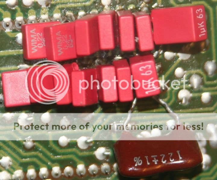
I definitely think there is something to be had using 0.22uF PPS SMT caps for bit decoupling with poss 1uF on the MSB. Also, 120pF on DEM can be PPS too. Short traces mean lots here ;-)
What are you doing for a clock? the eBay one with the /2 and /4 outputs?
On monday I'll order the rest of the stuff needed for the TPR's and Sanyo polymer 270uF/16V(to replace lythic caps around digital IC's), ZLH 470uF/16V(I've found them in Sweden now)
On Tuesday or Wednesday I'll order the clock and additional LM317T for the CD-50 I haven't started on yet, and maybe some adhesive copperfoil for shielding of the IC's.
What are you doing for a clock? the eBay one with the /2 and /4 outputs?
I definitely think there is something to be had using 0.22uF PPS SMT caps for bit decoupling with poss 1uF on the MSB. Also, 120pF on DEM can be PPS too. Short traces mean lots here ;-)
What are you doing for a clock? the eBay one with the /2 and /4 outputs?
I'll go with the "red clock" I think, with /2 and /4 outputs,
Might try the cap alternatives you suggest on the CD-50, don't want to aggrevate the (somewhat crappy) philips PCB more around that chip now in the CD-60.
Quite the improvement the 122pF DEM cap was
- Status
- This old topic is closed. If you want to reopen this topic, contact a moderator using the "Report Post" button.
- Home
- Source & Line
- Digital Source
- Marantz CD-50 and CD-60, TDA1541, CDM4/19