On his blog page Sunacchi released again his WAV to DSDIFF Converter that supports a direct conversion from 44.1 kHz/16 bit PCM WAV to DSD256 wav2dff.zip. The version is 1.5.
Moreover, YUKI-SAN, prepared an associated GUI program for the converter.
Wav2DffGui_015_010001.zip. The GUI program requires .NET 4.0 frame work installed in your PC.
The new version of WAV2DFF.exe enables a multi-thread processing and the use of 65536 taps in FIR calculation.
You need to put the WAV2DFF.exe, vcomp90.dll and Wav2DffGui.exe in the same folder.
Bunpei,
I downloaded the zipped files, extracted them and placed WAV2DFF.exe, vcomp90.dll and Wav2DffGui.exe in a new folder.
Running the programmes results in nothing but two "i" messages in what must be Japanese (I do not have Japanese character text installed in my system).
Any ideas what my mistakes are?
Cheers
David
The software with GUI works perfectly here. A 44k1 50MB WAV file is - after a few minutes on my 4 core computer - converted into a 760MB DSD256 file ")
There are a few options, and I do not understand most fo them:
normalise offset
Kaiser window alpha value
tap count
7th noise shaper pattern number
I used the default values.
Bunpei, thank you for sharing us the link to the software!
/S
There are a few options, and I do not understand most fo them:
normalise offset
Kaiser window alpha value
tap count
7th noise shaper pattern number
I used the default values.
Bunpei, thank you for sharing us the link to the software!
/S
The software with GUI works perfectly here. A 44k1 50MB WAV file is - after a few minutes on my 4 core computer - converted into a 760MB DSD256 file
There are a few options, and I do not understand most fo them:
normalise offset
Kaiser window alpha value
tap count
7th noise shaper pattern number
I used the default values.
Bunpei, thank you for sharing us the link to the software!
/S
+1 finally can use it, many thanks Bunpei & KOON3876
There are a few options, and I do not understand most fo them:
normalise offset
Kaiser window alpha value
tap count
7th noise shaper pattern number
These options are associated with internal parameters.
PCM to DSD conversion consists from two major steps.
1. Upsampling from 44.1kHz to 11.2896MHz (x 256)
Zero insertion and low pass filtering by a FIR digital filter
2. Delta-Sigma modulation
A. Tap counts
The number of taps used in the FIR digital filter
In general, the bigger number brings the better sounds. However, the longer processing time.
B. Kaiser window alpha value
The digital LPF uses a "window" function (the same term that appears in DFT(Discrete Fourier Transform))
Kaiser type window has a characteristic parameter "alpha" which determines a shape of window.
C. Normalization offset
In the FIR calculation for x 256 upsampling, a default normalization factor is 256. However, when an input sound data has a "clipping", it causes abnormality in the calculation. In order to avoid the error, an "offset" value for adjustment was introduced by Sunacchi as a work-around.
If your source contains clippings, you need to set a certain negative value, for example, -5 for this option. In this example, the effective normalization factor is 256+(-5)=251.
D. Pattern number for control parameter set
A noise shaper is a digital control circuit with a feedback. A z-transform notation is used for defining its transfer function. The noise shaper employed in the program is of 7th order. In general, the stability of the function can be estimated by the positions of "poles" and "zeros" in a Z-plane.
In this program, values of parameter zero are predefined in several sets. The pattern number is used to select one of the set.
To Koon,
If you find anything incorrect in the explanation above, please don't hesitate to point-out them.
Bunpei
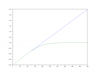
By the way.. this is compression function I'm using now.
attached plot shows input range 0.80 to 1.30 is compressed below 1.0 from value 0.90, very smooth
Compression: no effect for small signal, total dynamic range is compressed.
normalization: no effect for total dynamic range but all signal reduced
Code:
#include <math.h>

float sigmoid2(float input, float limit)
{
	//sigmoid function to compress input signal.
	//input signal = any range
	// 0 < limit < 1.0, compression starts from this value
	// 4.0 at gain comes from derivative of sigmoid function (at x=0 delta=gain/4.0 )
	// output is compressed between -1.0 to 1.0
	// convert_param is to convert sigmoid output(0.50 to 1.0) to (limit to 1.0)

	double convert_param = (1.0/(1.0 - limit))/2.0;
	double gain = 4.0 * convert_param;
	double sigmoid;
	double ret;

	if (input > limit)
	{
		sigmoid = 1.0 / (1.0 + exp(-1.0 * gain * (input - limit)));
		ret = limit +  (sigmoid - 0.50) / convert_param;
		return (float)ret;
	}
	if (input < -1.0 * limit)
	{
		sigmoid = 1.0 / (1.0 + exp(-1.0 * gain * (input + limit)));
		ret = -1.0 * limit + (sigmoid - 0.50) / convert_param;
		return (float)ret;
	}

	return (float)input;
}Compression: no effect for small signal, total dynamic range is compressed.
normalization: no effect for total dynamic range but all signal reduced
Attachments
By the way.. this is compression function I'm using now.
Dear Koon,
Thank you very much for showing your compressor code. I told this to Sunacchi.
As for applying your CUDA and AVX or SSE FIR converter techniques to WAV to DSDIFF converter, we are not ready for adopting them. None of us have any NVIDIA graphic cards on our PC.
Best regards,
Bunpei
Thank you, Bunpei-san, for the explanation of the parameters!
Rather advanced software conversion algorithms must be used. I want, of course, the best sonical quality possible, and long conversion times do not scare me, but even after reading your explanations a few times, I cannot decide what gives the best sonical conversion quality except that Tap Cpunt should be as large as possible.
BTW, porting the time consuming code into CUDA code, would be great. I mostly use NVIDIA graphics cards Aimersoft´s video conversion software that I use, can use NVIDIA graphic cards for around 5X faster conversion for certain type of files.
Best regards,
S.
Rather advanced software conversion algorithms must be used. I want, of course, the best sonical quality possible, and long conversion times do not scare me, but even after reading your explanations a few times, I cannot decide what gives the best sonical conversion quality except that Tap Cpunt should be as large as possible.
BTW, porting the time consuming code into CUDA code, would be great. I mostly use NVIDIA graphics cards
Aimersoft´s video conversion software that I use, can use NVIDIA graphic cards for around 5X faster conversion for certain type of files.Best regards,
S.
These options are associated with internal parameters.
PCM to DSD conversion consists from two major steps.
1. Upsampling from 44.1kHz to 11.2896MHz (x 256)
Zero insertion and low pass filtering by a FIR digital filter
2. Delta-Sigma modulation
A. Tap counts
The number of taps used in the FIR digital filter
In general, the bigger number brings the better sounds. However, the longer processing time.
B. Kaiser window alpha value
The digital LPF uses a "window" function (the same term that appears in DFT(Discrete Fourier Transform))
Kaiser type window has a characteristic parameter "alpha" which determines a shape of window.
C. Normalization offset
In the FIR calculation for x 256 upsampling, a default normalization factor is 256. However, when an input sound data has a "clipping", it causes abnormality in the calculation. In order to avoid the error, an "offset" value for adjustment was introduced by Sunacchi as a work-around.
If your source contains clippings, you need to set a certain negative value, for example, -5 for this option. In this example, the effective normalization factor is 256+(-5)=251.
D. Pattern number for control parameter set
A noise shaper is a digital control circuit with a feedback. A z-transform notation is used for defining its transfer function. The noise shaper employed in the program is of 7th order. In general, the stability of the function can be estimated by the positions of "poles" and "zeros" in a Z-plane.
In this program, values of parameter zero are predefined in several sets. The pattern number is used to select one of the set.
To Koon,
If you find anything incorrect in the explanation above, please don't hesitate to point-out them.
Bunpei
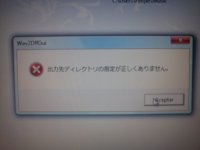
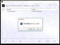
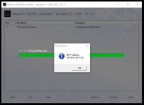
I have problems converting files, converter shows attached pic, coul you help me please?
The message is issued by GUI program. It says "Output file folder is invalid."
Please click "Options" button on the GUI program screen and select proper folder for your output file at the bottom line of the "Options" screen.
- Status
- This old topic is closed. If you want to reopen this topic, contact a moderator using the "Report Post" button.
- Home
- Source & Line
- Digital Source
- DSD Playback system, DSF Player + USB DDC + DSD Amplifier