Hi Coris
Just been made aware of two older Oppo 95's not starting up when you push the On button. I think it is likely that the caps in the olde switch mode PS have stopped working and needs replacement caps. Have you come across this before?
-Joe
Hi Joe
This issue it can occur by few different causes. The state of the SMPS is quite easy to check it, by measuring its outputs. If SMPS voltages are into right limits, then this cause it can be eliminated. In standby, the SMPS it provide power to the standby circuit (always powered), where the ON button is part of it. I will suspect this section when the device does not start up. Also the state of the switching chips on main board it can be another cause, for the device not starting up (not functioning switching devices - not providing power tot he system).
Hi Coris, changing the wiring to the new Dac, I broke the socket, and it has been impossible to fix which I have to change the pcb
Hi
I am still thinking it could not be a so catastrophic damage in your case. Could you provide a picture of the damaged area?
However, I am very sceptical about the possibility of finding a spare PCB for your device... A request about addressed to the Oppo himself, it could be another alternative as well...
Hi Joe
This issue it can occur by few different causes. The state of the SMPS is quite easy to check it, by measuring its outputs. If SMPS voltages are into right limits, then this cause it can be eliminated. In standby, the SMPS it provide power to the standby circuit (always powered), where the ON button is part of it. I will suspect this section when the device does not start up. Also the state of the switching chips on main board it can be another cause, for the device not starting up (not functioning switching devices - not providing power tot he system).
I have a similar issue. When I tap the power button, the device "powers up", as in the blue led lights up, but the display doesn't start, and it doesn't do anything. I have to long press the power button to turn it off, then power it up again. It powers up correctly the second time.
Would this be a similar problem?
I think here is more likely that the analogue section (its power system) is not working properly. One of the analogue power rails may not have the right voltages (due to the old filter caps failure).
The analogue power section it is monitored by some circuits. The result of this monitoring it is sent to the main processor. If the analogue power it fail, the device get looked somehow, or it shut down.
Clocking issues it may also cause similar behaviour.
The analogue power section it is monitored by some circuits. The result of this monitoring it is sent to the main processor. If the analogue power it fail, the device get looked somehow, or it shut down.
Clocking issues it may also cause similar behaviour.
Hi Coris here you are
An externally hosted image should be here but it was not working when we last tested it.
Hi Coris here you areAn externally hosted image should be here but it was not working when we last tested it.
Well, I could see in your picture a wire end (I suppose, coax) with a printed circuit pad attached on it. It could be more useful to see the damaged area on the PCB itself, for a better appreciation...
")
Hi Coris, I attached more photos
[url=https://subefotos.com/ver/?6d03d33fe036cb261da840dd68ef60c4o.jpg][IMGDEAD]http://thumbs.subefotos.com/6d03d33fe036cb261da840dd68ef60c4o[/IMGDEAD]
[IMG][url=https://subefotos.com/ver/?a352d07736f465e3fc68263b8653d5e0o.jpg][IMGDEAD]http://thumbs.subefotos.com/a352d07736f465e3fc68263b8653d5e0o[/IMGDEAD]
Alright. In my understanding, the issue it consist in a damaged pad on the PCB (resonator pad). For sure, such damage is not catastrophic for the entire PCB, and may not justify replacing of the whole PCB.
The damage occurred as result of soldering an enough big coax cable to a very fine PCB pad. The pad couldn`t sustain the high temperature of the soldering (in this case), and couldn`t resist to the high mechanical tension caused by a quite big coax wire.
My suggestions/recommendations:
- follow the trace coming from damaged pad (using a magnifier device), and find a new soldering point for clock signal insertion. This new soldering point it could be just the end of another component.
- appreciate the use of a very thin and flexible coax wire. In such cases, solder first the shield of the coax cable to a ground point (large and solid copper area on the PCB, very near to the signal insertion point). Scratch the ground area to create a soldering point. Pre-solder that ground point, before soldering the shield of the coax to it. Then route and solder the central wire of the coax to the signal insertion point. Supplementary, use some kind of glue to immobilise the entire coax quite near the soldering point on the PCB. Manipulate the coax only after the glue it hardened.
- use an appropriate soldering iron (low power and temperature controlled) in such fine operations, and do not keep too much the soldering tip on the soldering point. As soon as you see the soldering melting, remove the soldering tip at once. Use an appropriate flux to improve the joint, and minimise the soldering time.
- (optional, send me that board for fixing).
Last edited:
Are these leaky caps
hello everyone,
I got this BDP 95 used recently. The fan seemed to run a lot, so I opened up the case.
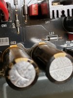
I noticed the following brown residue under a couple of caps in part of the power supply. Are these a sign of caps on the way out ? There doesn't seem to be bulging or visual distortion in the caps.
Thanks for any suggestions
hello everyone,
I got this BDP 95 used recently. The fan seemed to run a lot, so I opened up the case.
I noticed the following brown residue under a couple of caps in part of the power supply. Are these a sign of caps on the way out ? There doesn't seem to be bulging or visual distortion in the caps.
Thanks for any suggestions
Attachments
The fan continuous spinning it may be caused by failure of the thermal circuit, which it control this fan (inside the main processor), or of the fact that main processor it always work hot. In this last case, the fan should not run just at power on, but somehow later.
Another possibility is that the fan it was wired so (not original approach) to spin always, for an supposed improved ventilation.
The substance seen at the base of some caps on original PSU it may not be a residue coming from the caps, but a glue used in board manufacturing process. Oppo used a such glue approach in all its player models, to immobilise some caps to the board.
If that substance it can easily be removed (cleaned out), then it mean it come from the caps. As normal, when a cap it leak its electrolyte, this is because a internal pressure. Such pressure it may also inflate the cap (not the case in your picture).
All right. About the fan: the fan behaviour is not just unusual. It start up running when the processor temperature reach a quite high level (stupid design of that Oppo model). The fan it will however not contribute to much to cool the processor. The problem is that the processor it reach too fast a high temperature. An audio playback should not cause an important heat dissipation on that processor. This is more normal when playing back video or BD discs. The processor high working temperature it can be caused by the degradation of the thermal paste capabilities to transfer the heat to the enough insufficient, heatsink. The processor get better cooling when the cover is removed...
It is not very difficult to remove the metal plate mounted over the processor and then replace the old thermal paste (or maybe the thermal pad) with a new one. If it is placed a thin pad there, then it is better using thermal paste. Also that processor it have a thermal pad placed under the board, to improve the heat dissipation to the chassis. That pad it could be degraded as well. However, try first improving the thermal transfer to the heatsink placed on the top of the processor...
About the substance under the caps: that is not a leak from the caps, but a glue used to fix the caps to the board, or even it may be meant preventing an accidental corrosion on board, in case that caps should leak for one or another reason.
Well, we cannot know exactly what it was in the mind of the designers who decided to apply that glue under some caps on boards of Oppo devices... There is not necessary to remove that substance.
Last edited:
Hi Coris & Joe,
just need a little help getting my old BDP-95 going again.
Fault.
Connect to power - red standby indicator comes on.
Hit power button - indicator change to blue & oppo displayed on screen.
Press draw open button & draw opens - insert disc - close - display still shows oppo
& disc not read.
After about 30 - 40 seconds buttons button become unresponsive & a small relay click can be heard.
Holding power down for several seconds it goes back to red standby.
Checked voltages on linear PSU board & I have +15, -15, +9.7 on TP17 & +1.5 on TP18.
SMPS appears to be outputting correct voltages.
Checked all SMPS caps with in circuit ESR meter & they look ok.
Any ideas?
Thanks Clay
Some questions...
If you are not trying to playback any disk, the player it work well?
You got the Hello message on display and the start screen on your monitor? You can navigate through it?
You can playback files?
It become the player unresponsive even if you are not pressing any button, after powering it up?
It is disk spinning inside after loading? You should see on your monitor the result of the disk loading. If not successfully, then the player display on monitor the message: No disk, or Unknown disk.
You may also see on your monitor the messages/animations when the tray of the drive it open up, and after it close. It this happen?
I also suggest you measure the power voltages after the device it become unresponsive.
Last edited:
Hi Coris & thanks for getting back to me.
OK I tried connecting a monitor & it displays Oppo on start up but that's all.
It it not possible to enter any menus or set up mode.
I tried to get into the menu even before it becomes unresponsive but no go.
No I can not play any files as no menu access.
Yes it becomes unresponsive after about 30 - 40 seconds even when touching no buttons - you hear the usual relay click after 30 -40 seconds.
I don't think I could hear the disk spin up but will re check.
The voltages were the same after it become unresponsive but I will recheck as well.
One more bit of info.
I carefully visually examined the SMPS board & did notice a tiny bit of green corrosion
on one leg of the four pin opto-coupler. The part is no longer available but I replaced it with a similar specked Vishay device.
After that it powered up normally (& worked)
Unfortunately when I tried it a few days later it had the same fault as before.
I have ordered another close equivalent opto-coupler so I will try that.
Thanks again
Last edited:
I do not think the problem is in SMPS. So far you have the right voltages on its outputs, that is well working. The small corrosion on that pin is not an issue in the first instance. You can also try the SMPS disconnected form main board, measuring its outputs. If you get 5vDC and 15vDC, then all is all right. If these voltages it keep their values while the device it freeze up too, then no problem there.
I suspect one of the rest of the small SMPSes planted on main board, it may fail, after 30-40s, when the whole device freeze. The symptoms you describe, it looks to me as a clock failure, or the power up sequence it stop for some reasons. The system get clocked in the beginning, when it start up as usual, but soon something occur, and either the clock stop running, or some controls it cannot be done, or there is a firmware dysfunction somehow. The power up sequence it not run as it should. Something is missing or it stop in this process. The clock systems it cannot be defective, but the PSU which it power it, can fail. It is not impossible that the main processor itself (one of its internal sections) it fail, or one of the DC/DC converters which it provide power to main processor, it can fail.
I will suggest disconnecting the analogue board, and removing it completely. The player it should work and boot up normally without it. Then you can measure more on the main board power system (after the device it freeze), trying finding clues for the problem. Interesting to see what happen when the analogue board is removed from system...
Last edited:
I am also thinking that a too high residual HF noise on SMPS DC outputs it can as well disturb the power up sequence... The DC voltages it may be as it should, but one should know what about the level of the HF noises too...
This hypotese it may explain why you got a normal power up after previous intervention on SMPS...
This hypotese it may explain why you got a normal power up after previous intervention on SMPS...
- Home
- Source & Line
- Digital Source
- Upgrading & modding new Oppos, BDP-93 & BDP-95