The ess sabre 9028 pro is advertised by ess as a drop-in replacement pin compatible with the sabre 9018.
The sabre 9038 pro is not. It carries an additional 5v input, so you could not directly perform a drop in replacement like you could when going from 9018 to 9028. I read elsewhere that the 9028 is sonically an improvement, but it does not carry a night and day difference between the two.
Understood, it is not compatible then....., thanks for clarifying the point.

I remembered reading this, ( In the link i attached ) apologies :
Clearly we see the ESS Sabre reference DACs in the Sonica DAC (ES9038Pro) and BDP-105 (ES9018) perform extremely well...
Not certain which ess chips the bdp 105 utilizes - the 9018 or the 9028 (pretty certain it is the former since it is just a revision of the bdp-95). The bdp 105 was released before the incarnation of the ess 9038 pro but I believe it was around during the ess 9028 run. It may be possible that later versions of the bdp 105 utilized the 9038 pro. But then oppo would not call it the bdp 105 anymore.
This is speculation on my part but I am pretty certain that is the case, unless someone could prove otherwise.
This is speculation on my part but I am pretty certain that is the case, unless someone could prove otherwise.
Last edited:
How about nichicon low esr caps? They should do just as good of a job as Panasonic caps.
ESR is better on the RIGHT Panasonic caps. Not all the same.
Lelon caps are good too.
Steve N.
You have 22 voltage regulators on the audio board AND you are using Paul hynes voltage regulators on all 22 regulators?
Do you have any bdp9 porn you would like to share with us?
Paul Hynes technology. I designed the regulators.
Steve N.
Steve - did you replace all the regulators on the audio board (22 of them?) with your regulators? Are they running in shunt or serial or both? I am still thinking of going with tentlabs regulators for the 3.3v and burson for the 1.2v regulators.
I use Paul hynes ps and regulators on my turntables.
Also, would you mind sharing which caps you replaced on the audio board with your solution of caps?
I've been meaning to upgrade my bdp 95 for quite some time, but other projects have taken precident.
I use Paul hynes ps and regulators on my turntables.
Also, would you mind sharing which caps you replaced on the audio board with your solution of caps?
I've been meaning to upgrade my bdp 95 for quite some time, but other projects have taken precident.
Steve - did you replace all the regulators on the audio board (22 of them?) with your regulators? Are they running in shunt or serial or both? I am still thinking of going with tentlabs regulators for the 3.3v and burson for the 1.2v regulators.
I use Paul hynes ps and regulators on my turntables.
These regulators are serial, some with small pass FETs and some with large pass FETs on heatsinks. They have all been speeded-up, except the analog ones. For Digital, you need fast regulation.
Also, would you mind sharing which caps you replaced on the audio board with your solution of caps?
They are not "replaced". It is my product. My mix of decoupling caps is one of my trade secrets, sorry. Maybe if someone buys my component business, they will share this, or after I retire in a few years.
Steve N.
Empirical Audio
replacing stock clock in Cambridge 851c
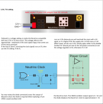
I too am interested in replacing my stock clock in my Cambridge Azur 851c to a NewClass D Neutrino Super clock and while the instructions from the manufacturer are simple to follow, I don't have a schematic for the player (it is still in production). I didn't have any problem finding the power for the clock, but I am having a problem finding the two caps that I need to remove in order to install the clock. I have attached photo of the board below with the hope that someone can help me identify the right caps to remove. Since they are surface mount devices, I don't want to make a mistake-- replacing them would be difficult. Thanks in advance to anyone who can help.
I too am interested in replacing my stock clock in my Cambridge Azur 851c to a NewClass D Neutrino Super clock and while the instructions from the manufacturer are simple to follow, I don't have a schematic for the player (it is still in production). I didn't have any problem finding the power for the clock, but I am having a problem finding the two caps that I need to remove in order to install the clock. I have attached photo of the board below with the hope that someone can help me identify the right caps to remove. Since they are surface mount devices, I don't want to make a mistake-- replacing them would be difficult. Thanks in advance to anyone who can help.
Attachments
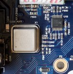
I am having a problem finding the two caps that I need to remove in order to install the clock.
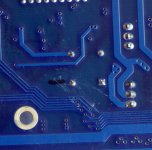
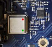
There are no caps to remove, remove existing oscillator and identify which of the four pins are the output of thr oscillator and that becomes your input.
See where it says "X1" near the corner of the oscillator, it is printed on the PCB. That corner should be it. See "Red" below. The "Green" is your Ground.
Attachments
Thank your of your suggestion. Have you worked on this machine before? Is it that this design doesn't have the caps to remove?
Please excuse my skepticism. It is curious to me that the manufacturer of the replacement clock would put a diagram on his site-- as a part of the instructions how to install his clock-- that the two caps coming out of the original clock have to be removed. Please advise.
Thanks.
Please excuse my skepticism. It is curious to me that the manufacturer of the replacement clock would put a diagram on his site-- as a part of the instructions how to install his clock-- that the two caps coming out of the original clock have to be removed. Please advise.
Thanks.
Thank your of your suggestion. Have you worked on this machine before? Is it that this design doesn't have the caps to remove?
Please excuse my skepticism. It is curious to me that the manufacturer of the replacement clock would put a diagram on his site-- as a part of the instructions how to install his clock-- that the two caps coming out of the original clock have to be removed. Please advise.
Thanks.
They should have included two sets of instructions, you have only been given one, replacing a resonator with a clock, not replacing an oscillator, which is what you have got.
There are no caps to remove in your case. What you are removing is a powered oscillator (it should be 3.3V) and not a crystal, which is basically as resonator that needs those caps. The new clock is also a powered oscillator (it should also have its own 3.3V). So in a sense you are replacing like for like. Probably done a thousand of clocks by now. If Coris is around (he is likely sleeping now), he will tell you the same thing.
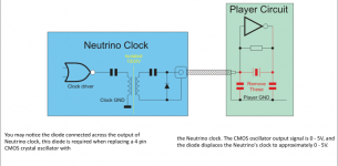
Thanks again for the clarification. In terms of the power supply for the new clock, it says that it needs 12v going in but the clock runs on 3v. Does that mean that I have to find a 12v source for it in the player and then before it gets to the clock, it steps it down to run the clock 3v? Or do I find 3v in the player and use that directly? I have attached the instructions from the manufacturer's site. Thanks for you help so far.
Attachments
- Home
- Source & Line
- Digital Source
- Upgrading & modding new Oppos, BDP-93 & BDP-95