Let me explain very clearly how the stock 95 power supplies are: First there is unregulated plus and minus 21 volts (would have been nicer to configure the tranny for about plus and minus 18.5...for heat sake). On the separate power supply board there are three preregulators. A plus and minus 15 and a plus 9.74. All done with 317 and 337 regs. The power then goes to the output board where the plus and minus 15 go through another set of regs to make plus and minus 10 for the opamps (317 and 337 again). The plus 15 volt also feeds the two 3.3V regs for the analog part of each DAC. These regs are super reg types....that is, they use an opamp and a discrete pass device.....they are not monolythic regs. This is well thought out for a $1000 thang. The 9.7 Volt supply feeds all the "digital" supplies....the 1.2v and the 3.3v regs. The analog 3.3 Volt supply does feed the 54 meg oscillator (this should have been another reg for sure). Oppo is probably feeding the 3.3V analog supply off the plus 15 volt supply to keep it from seeing the noise on the digital supplies.
There are 3 preregs and 10 regulators on the output board. This is pretty darn serious for a $1000 unit that smokes most $3000 thangs out there. Yes, you can use more and better supplies and also up the frequency on the clock....but this is one hell of a nice machine for $1000.....in fact, its incredible what they give you. But of course, we are perfectionistic tweakers so we will do whatever we can to improve it. However, what Oppo did is pretty darn nice.
Thanks for the details and a accurate description af the player power system. You right!
You may be right too when you talk about the price and the corresponding quality, but here I personally am not fully agree with you. First Oppo do not "give" a product out on the marked, but they sell it and one have to pay for it. When you pay for something you may also pretend that quality level you expect it for that you pay for. Here is the difference: somebody can be satisfy, somebody not, for the same price one it pay... But, anyway this is something else...
In my opinion, with almost the same price, this player could be one of the rally best on marked... There is about design here, not about (or less) about components... The design costs is included in this 1000$ class price they sell the player. The design could be much better and not so unprofessional how it is in this case. This is only a big shame for Oppo as a high end products company....
I just measured yesterday an 0.5mV DC level between the GND point input from analogue power supply on the audio board, and the GND point of the final output op amp on the same board... This voltage level on the GND plane is variable as the measurement point could be near or quite far from the main (analogue) power supplies. As known this output board of BDP95 is very (unnecessary) wide. So, what for use an low noise power supply with eventually nV noise level, when one have a possible 500µV noise level between different points on the GND plain? I still think that the best solution is in this case, using of local power supplies/regulators (shunt regulators), quite near to the corresponding stage/opamps. I will try to find a solution for corresponding modifications in this field...
Last edited:
Thanks for the details and a accurate description af the player power system. You right!
You may be right too when you talk about the price and the corresponding quality, but here I personally am not fully agree with you. First Oppo do not "give" a product out on the marked, but they sell it and one have to pay for it. When you pay for something you may also pretend that quality level you expect it for that you pay for. Here is the difference: somebody can be satisfy, somebody not, for the same price one it pay... But, anyway this is something else...
In my opinion, with almost the same price, this player could be one of the rally best on marked... There is about design here, not about (or less) about components... The design costs is included in this 1000$ class price they sell the player. The design could be much better and not so unprofessional how it is in this case. This is only a big shame for Oppo as a high end products company....
I just measured yesterday an 0.5mV DC level between the GND point input from analogue power supply on the audio board, and the GND point of the final output op amp on the same board... This voltage level on the GND plane is variable as the measurement point could be near or quite far from the main (analogue) power supplies. As known this output board of BDP95 is very (unnecessary) wide. So, what for use an low noise power supply with eventually nV noise level, when one have a possible 500µV noise level between different points on the GND plain? I still think that the best solution is in this case, using of local power supplies/regulators (shunt regulators), quite near to the corresponding stage/opamps. I will try to find a solution for corresponding modifications in this field...
the analog board ground plane can sit at different DC potential in respect to the GND point of the analog power supply... and still have remarkably low noise performance. What you measured with the multimeter does not mean the analog board ground plane is noisy.
the low noise regulators should definitely be located very close to the IC's.... the long power supply traces between regulators and IC's on BDP95 analog board is probably the biggest flaw of the design... this can be compensated somewhat with the correct local decoupling capacitors' values / types / placement location…. I also don’t like polystyrenes…
still, I think that is a lot of a player for $1000.
Boky
Yes, does not mean that the analog board ground plane is noisy, but can easily be in situations like this... Well, when I will get (soon) my oscilloscope it will be possible for me to analyse closer this aspect.
By the way, I can see that interconnection between audio board and the motherboard is made by a flat cable which use only the pins on one side of the respective connectors. On the audio board are printed names of signals for both sides of that connector. It could be for an future upgrade of the system, or can some of the another signals be valid too for this model? I just think about what to connect those boards with a two side flat cable...
Can have the SATAx signals named on this board`s main connector interface, something to do with SATA interface?
Have somebody get in this before?
I think the stock design of this player is a classic case of the accounting people in the company putting pressure on the engineering staff(at least I hope their engineers are not as incompetent as the design implies). The accountants no doubt say "will the average person hear the difference?", when demanding yet another corner be cut. The details you've uncovered about the design are just shocking, and I think completely inexcusable.
And gee, I thought it sounded pretty good design-wise based on Ric Shultz's detailed description of the supply topology - particularly at this price point.
One thing I want to point out is that the 317/337 regulators require a minimum of 3.5V across them to meet their full specifications (based on specs and experience) and when you factor in 10% low line as a design criteria that puts the raw dc input voltage to the regulator at slightly over 20V for nominal line - so even the transformer output voltage seems a reasonable choice if you want to maintain good regulator performance over temperature and input voltage range.. The one one issue I would quibble with is the oscillator supply, and that obviously from the bean counters perspective was probably at the point of diminishing returns. Seems competent enough even if not brilliant..
Let me explain very clearly how the stock 95 power supplies are: .......................... But of course, we are perfectionistic tweakers so we will do whatever we can to improve it. However, what Oppo did is pretty darn nice.
Thanks for the explanation.
Let's forget about the cost/performance view but only from perfectionist view. Just interested to know what would you have done to the power supply in your tweak ?
Thanks for the explanation.
Let's forget about the cost/performance view but only from perfectionist view. Just interested to know what would you have done to the power supply in your tweak ?
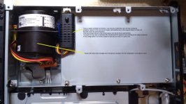
You know? I just removed it...It is possible I will use it again, but modified accordingly...
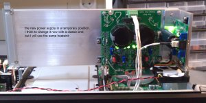
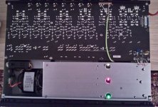
I`ve used instead the Twisted Pear shunt regulators power supplies. I replaced too the Rotel toroid, with two separate toroids. It was fine to have the Rotel trafo in his place, but I need 3 AC sources (for +/-15v PSU and +9v (12v).
Those TP shunt power supplies are very good, but it seems that are not quite in right place in this case. They get too hot for the volume of this player enclosure. So, I think I will go back to the classic regulators as primary PSUs, and then I will use shunt regulators locally, near every stage. I think this is a much better solution, and a less heat dissipation.
Please note that in case the original PSU is changed with another one, one have to simulate the signal used by Oppos designers to give to the main processor the message that the power is OK, or something like this (I`ve not investigated yet this very close. I have other priorities...). This signal is an 1,5v DC level (OVP-test). I`ve used an potmeter to create this level from the 9v new PSU. Is not necessary to be exactly 1,5v. It works well for me even with an half of this level...
Attachments
Last edited:
Referring to my previous posts and attached pictures.
I have to say that I`ve abandoned the idea to use the shunt regulator power supplies for my BDP95. At last two of the earlier pictures here do not reflect the reality for today...
These shunt power supplies are good enough, but not in this case, when the enclosure is quite full and the ventilation is not adequate for such heat dissipation.
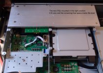
I just build it from scratch two another (serial) power supplies based on LM2991/2941 and placed then on the same aluminium plate. I found an R core 40W transformer which deliver 2x15v/9v AC. I have now +/-15v for the output stage. I used the on board regulators, modified for adjustable output, and I feed the I/V stage with +/-12v. +9,5v for the rest.
These new power supplies provide a very good stabilization and the temperature on the heat sink do not exceed now 28 degree. This is very well! Before I had to struggle with 50 degree...
With a fine tuning of these supplies and right set up for the offset level in I/V stage, I have now an offset on the RCA output as low as 0,2mV.
I think now that the best solution for power supplies in this case is to use as primary supplies the serial one, and have local shunt regulators right beside every stage involved in audio processing (digital/analogue).
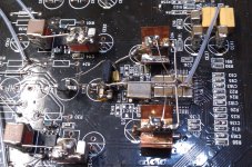
By the way, I use now a 133,3 Mhz clock for ESS9018 and local shunt regulators for AVCC of the chip and an shunt regulator too for the clock oscillator. The I/V and output stages are also modified...
Now, the finally result of the audio stage is not so easy to describe, but in one word is just unbelievable.
I have to say that I`ve abandoned the idea to use the shunt regulator power supplies for my BDP95. At last two of the earlier pictures here do not reflect the reality for today...
These shunt power supplies are good enough, but not in this case, when the enclosure is quite full and the ventilation is not adequate for such heat dissipation.
I just build it from scratch two another (serial) power supplies based on LM2991/2941 and placed then on the same aluminium plate. I found an R core 40W transformer which deliver 2x15v/9v AC. I have now +/-15v for the output stage. I used the on board regulators, modified for adjustable output, and I feed the I/V stage with +/-12v. +9,5v for the rest.
These new power supplies provide a very good stabilization and the temperature on the heat sink do not exceed now 28 degree. This is very well! Before I had to struggle with 50 degree...
With a fine tuning of these supplies and right set up for the offset level in I/V stage, I have now an offset on the RCA output as low as 0,2mV.
I think now that the best solution for power supplies in this case is to use as primary supplies the serial one, and have local shunt regulators right beside every stage involved in audio processing (digital/analogue).
By the way, I use now a 133,3 Mhz clock for ESS9018 and local shunt regulators for AVCC of the chip and an shunt regulator too for the clock oscillator. The I/V and output stages are also modified...
Now, the finally result of the audio stage is not so easy to describe, but in one word is just unbelievable.
Last edited:
What shunt regulators are you using on the DAC and clock? Schematic?
Hi
I`m using TL431 and schematics are right out from the datasheet. Nothing very special this time. But I have to make a correction referring to my previous post and after reviewing my papers... I actually have been using for ESS9018 - AVCC two low noise regulators (L/R) based on MIC5209, also schematic from datasheet. In my opinion, very important is decoupling/bypassing capacitors soldered closest as possible to the load/chip pins.
I have to say too that the BDP95 mods was more as an experimental project for make my self an impression about ESS9018 capabilities. As this Oppo project is now almost finish, I will focus more from now on on Buffalo (I got it one in the last time...). With this kit/PCB is more easy to try new experimental levels, trying better solutions, and much more easy to scope and measure the parameters...
After I took it a very closed look on OPPO`s BDP95 I can only say that I`m very, very disappointed by the Oppo design of the audio dedicated stage/board and it`s power supply.
Attachments
still, I think that is a lot of a player for $1000.
Boky
You are right - dear fellow Sydney sider.
But the single most worst source of noise in digital players does NOT come from the power supply.
NO?
It comes from the DAC itself. A bit like getting stuck in a hermetically sealed room. We tend to pollute our own environment and so we need ventilation.
Ventilation is of course not the answer here.

But the question is how you are going to treat THAT noise as well as the PS noise.
The best solution is to shunt as much noise as you can into the groundplane at lowest Z possible, and also form a 2nd order filter from the PS. That way we treat both the primary and secondary sources of noise. But very few actually do this or even aware that it should be done.
I repeat, the primary source of worst kind of noise comes from the DAC itself.
I can demonstrate an Oppo that does just this, has no post-DAC active NFB circuitry and other niceties, so we are talking something fully fleshed out.
Cheers, Joe R.
Joe,
What is the purpose of your post on a DIY thread? You tell us of some must do technique that you are selling and do not tell us how to do it. What, you want us to buy it? Are you advertising? As you know, I modify Oppos too but I would not come on here and say I have the solution to mankinds problems and I can demonstrate it to you if you buy my product. I have some tact (not a whole lot...he he). This is a DIY forum.....come on...tell us how you do this. Give us the formula.
What is the purpose of your post on a DIY thread? You tell us of some must do technique that you are selling and do not tell us how to do it. What, you want us to buy it? Are you advertising? As you know, I modify Oppos too but I would not come on here and say I have the solution to mankinds problems and I can demonstrate it to you if you buy my product. I have some tact (not a whole lot...he he). This is a DIY forum.....come on...tell us how you do this. Give us the formula.
Joe,
What is the purpose of your post on a DIY thread?
My amusement?
Cheers, Joe R.
I do not think I need to defend my DIY credentials. Go back to Post #2 and my website has plenty of free DIY stuff.
Often regulators are more than just mm (often can be measured in many cm) away from the DAC. There is inductance there. Often there is less than adequate 100n caps to decouple the inputs on the DAC. Simple, beef them up!. I won't tell what I use, but you will now have something along a 2nd order LC filter from the PS and indeed it may be argued that the inductance now works in our favour. It will also effectively dampen much noise out of the DAC
Fair enough Ric?
Cheers, Joe R.
Last edited:
You are right - dear fellow Sydney sider.
But the single most worst source of noise in digital players does NOT come from the power supply.
NO?
It comes from the DAC itself. A bit like getting stuck in a hermetically sealed room. We tend to pollute our own environment and so we need ventilation.
Ventilation is of course not the answer here.
But the question is how you are going to treat THAT noise as well as the PS noise.
The best solution is to shunt as much noise as you can into the groundplane at lowest Z possible, and also form a 2nd order filter from the PS. That way we treat both the primary and secondary sources of noise. But very few actually do this or even aware that it should be done.
I repeat, the primary source of worst kind of noise comes from the DAC itself.
I can demonstrate an Oppo that does just this, has no post-DAC active NFB circuitry and other niceties, so we are talking something fully fleshed out.
Cheers, Joe R.
I could not agree more with you!
.... there’s one tiny difference… my measurements have shown microprocessors generate most noise, if there’s a microprocessor on the same PCB with DAC(s)… closely followed by DAC’s, then decoders…
… I also use the exact same 2 techniques you mentioned (suggestion: try wide silver ribbons “low noise feeds” straight from the power supply lowest noise point to the noisiest chip’ ground fill…)
Boky
Joe,
I have seen Allen Wrights posts and pics where he describes/shows using large value ceramic bypasses on the digital chips. I thought these newly described filtering techniques were something new. Many people do this already. Look at the last pics of Coris's DAC. A ton of large value ceramics directly on top of the DAC chip. If you like inductance for filtering then why not put a ferrite bead on the power supply lead right at the DAC chip and then your large bypass. Personally, I have found that ferrite beads do not sound good.
Do you put these ceramics on the modded Yamaha player? I had one here that I did further mods on and I did not see any additional bypasses on the DAC chips (maybe under the board?).
I have never warmed up to the sound of ceramic caps. For instance, the VSE modded Yamaha that I had here had .1 ceramic caps on the power supply next to one of the AD844 op amps on the output board. I replaced them with my modified Wima poly prop caps (I dremel off the steel leads and replace them with pure copper and I mark the caps for outside foil and also damp them). The sound was noticeably better with the modded Wimas.
I find the "sound" of regulators to be very important. Most regulators do not "sound" very good so using multiples of them (pre-regs) actually just adds the bad sound and does not actually remove perceptive noise or make for more transparency. If possible I like to use shunt regulators with cascoded current sources and all discrete implementation (like Allen Wrights regulators in the original Sony mods.....the even more complex Salas regs are even better but are so large they don't fit in much OEM gear). My sense is that the TL431s used in the latest VSE mods are not as good (they certainly cannot measure as well). Maybe he ran out of those mosfets he was using in the old mods?
There is so much to learn. This game is endless. I feel like a beginner and I have been doing this since 1976!
There is so much to learn. This game is endless. I feel like a beginner and I have been doing this since 1976!
That is so.
Yes, on the Yamaha you'd need to look under the PCB.
No, I wouldn't use ferrite beads either.
Allen use of LM431? Well, mea culpa, I made that board. But agree on CS fed shunt regs in principle. We've been doing it since the very earliest 80s.
Cheers, Joe R.
Just a quick one re LM431. The resistor divider it needs, not sure what others do, but the upper part of the diver (hits the +) must be bypassed with a really decent electro cap and force it into AC unity gain, and then another cap across the shunt as a whole - it can make or break the LM431.
Cheers, Joe R.
Cheers, Joe R.
I find the "sound" of regulators to be very important. Most regulators do not "sound" very good so using multiples of them (pre-regs) actually just adds the bad sound and does not actually remove perceptive noise or make for more transparency. If possible I like to use shunt regulators with cascoded current sources and all discrete implementation (like Allen Wrights regulators in the original Sony mods.....the even more complex Salas regs are even better but are so large they don't fit in much OEM gear). My sense is that the TL431s used in the latest VSE mods are not as good (they certainly cannot measure as well). Maybe he ran out of those mosfets he was using in the old mods?
Ric, Have you tried Guido Tent's shunt regulator boards? They are small. They appear to be a relatively conventional circuit with CCS and opamp error amp.
Rob.
Ric, Have you tried Guido Tent's shunt regulator boards? They are small. They appear to be a relatively conventional circuit with CCS and opamp error amp.
Rob.
Last edited:
My sense is that the TL431s used in the latest VSE mods are not as good (they certainly cannot measure as well). Maybe he ran out of those mosfets he was using in the old mods?
No, he didn't. The 431 was only used on one board - and it was made by yours truly. So blame me.
Cheers, Joe R.
- Home
- Source & Line
- Digital Source
- Upgrading & modding new Oppos, BDP-93 & BDP-95