Yes, try the oscon; 10-68uF is quite large enough - it has to charge-up through the chips internal divider, so you don't want too long a start-up time. If the 47nF thingy is SMT, leave it in place too.
This dac was used in a lot of good equipment. DPA used it in various PDM1 / Little/Bigger Bit designs. They used an active, low-noise 2.5v voltage reference with buffer to drive these pins, so if you want to really experiment...
The full Philips 'CD7' chipset is to use the SAA7350 to generate the bitsream, and the TDA1547 solely to decode it. It's a pairing capable of stunning sound.
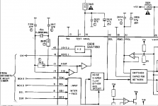
Hi Martin, can you give me an advice of how should I conenct a direct isolated 2,5V supply line to feed the existing quartz? Attach you below the schematics of CD42 showing the original circuit. I'm a bit confused of what is the Xin & Xout 7350 pins. I have built an external power supply for this raill. I did some measurments across 3645 - 1K resistor. 2,25V at the chip side (pin 15) and 2,30V the crystal side. In the option that I'll atempt to connect the output of an OSC clock chip and remove the related crystal circuit , to what pin should I connect the output clock signal of the external OSC? to pin16? I hope my questions make sense. Regards
Attachments
Not sure if this was meant by Pete, but pin12 is the supply for the digital section of the 7350, it might be worth trying to feed this from a separate regulator.
Cheers, Georg
Thanks Georg for your reply. Dedicated supply rails for all 5V supply inputs of 7350 is something that I have in my mind for further upgrade. The discrete DC input of Crystal is more related to isolate power supply from the noise created by the crystal itself and "infect " the DC lines to other chips. Of course a well regulated, filtered and bufferd DC line is always welcome to any circuit. Moreover the voltage that Pete and Simon were talking about was at the 2,5V level and not 5V.
- Status
- This old topic is closed. If you want to reopen this topic, contact a moderator using the "Report Post" button.