Ok, this ought to be fairly simple, or not.
Does anyone know their way around the actual laser diodes that are typically used (by the millions apparently) in CD transports?
These are the little gold plated things... not the entire assembly.
ALTHOUGH if you are in a place that has access to the entire assembly, I'm interested in that too...
What I want to know is their typical operating parameters, AND what output levels they are, beamwidth too! Why? I want to replace the laser diodes in a few very good transports that have become "blind". I have dissected one and it is very much removable. Without knowing this, there are too many variants to pick a good replacement.
I see that they come in 4 pin and three pin.
I see many on the market, even in Digi-Key and Mouser.
BUT, which one is going to be a good replacement, how to choose??
So, any CD transport Laser Diode Guru's??
_-_-bear
_-_-bear
bear said:Ok, this ought to be fairly simple, or not.
Sorry to disappoint you, but read this.
"Even replacement with an identical laser diode would prove challenging without the optical alignment jigs and specialized test equipment."
This is a thankless task. You are better off replacing the whole assembly which is generally available as a separate part. Also there is a sensitivity trim, that little tiny pot on one of the boards, that needs to be adjusted using a proceedure that you probably can't find documented anywhere.
I imagine that you were not lucky in finding the whole optical pickup as a spare part.bear said:
....
BUT, which one is going to be a good replacement, how to choose??
_-_-bear
Anyway, concerning the laser diode, first it is best to try to determine what is the original model used, and do your best to find it. In case it is obsolete at least you have a datasheet and a starting point to find a compatible replacement. Laser diodes aren't really 'plug and play' but you can expect similar characteristics for this application from several manufacturers. Obviously you have to exclude from your search diodes for CD burners or DVD, DVD writers... Only those for CD or Video CD are well suited
What to look for:
- same emission point from reference plane
- same package type and polarity
- obviously same wavelength and power. Max. power can be higher, no problem, but it needs to have:
- same threshold current which actually can be a bit lower than original (but not higher)
- same or very close differential efficiency
- preferably the same photodiode monitoring current
Luckily the last three conditions will ensure about the same optical power, but there's no guarantee - fine adjustments might still be needed. At least you're in the same ballpark as the original and you don't need to change the value of the little pot...
")
Think of replacing the laser pickup before but drop it when I can find the assembly.
Before you replace it:
1. did you confirm there is no laser coming out from the len by using your mobile phone camera to check the beam?
2. did you try to adjust the tinny trim pot on the assembly. It is for the receiver gain, that might help a little.
Good luck.
Before you replace it:
1. did you confirm there is no laser coming out from the len by using your mobile phone camera to check the beam?
2. did you try to adjust the tinny trim pot on the assembly. It is for the receiver gain, that might help a little.
Good luck.
sidiy,
Thanks!
right, and if I could figure out a way to ID the laser diode part, then it might be relatively easy. That's the issue. Iirc, no visible part number - and if there was one, not sure how to find the mfr.
I suspect strongly that there is very very little difference in the output lumens between most diodes in most players of similar vintage and construction...
However:
- same emission point from reference plane
A function of the physical internal construction and the package?
- same package type and polarity
Well, yes, perhaps this can be determined by testing in situ?
(polarity, at least)
- obviously same wavelength and power.
I would think they are all pretty much dead bang the same.
Max. power can be higher, no problem, but it needs to have:
- same threshold current which actually can be a bit lower than original (but not higher)
Mmmm... how to determine empirically using a unit that has now low output?? Or can one pick amongst a given mfr's offerings for one with the lowest threshold current?
- same or very close differential efficiency
Please explain this spec? I am unfamilliar with it.
- preferably the same photodiode monitoring current
Oh? I has its own photodiode internal for feedback??
Regards,
_-_-bear
PS. can you ID any Laser Diode that is/was known to be used in any CD player - especially of vintage mid/late 90s?
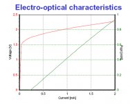
bear, here's a picture of the characteristics of one of those little lasers in a laser mouse. It gets across the idea. There is a lasing threshold and a slope of optical power out vs current which is pretty linear. The diode voltage is on the high side like an LED. You need to match the slope to get the same modulation depth, IIRC that is what the SMT pot is for. I don't remember when the power monitoring diode is built in or when there is a beam splitter and a separate detector.
If you're working with a CD writer I shouldn't have to tell you that they are NOT eyesafe.
BTW I don't think adjusting the pot while the CD is playing is an option, during mfg the whole thing is put in a test jig. They really are assembled to optical tolerances that you would not believe.
Here's an info link too http://members.misty.com/don/laserdio.htm#diocss4
Attachments
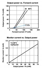
Here is a typical datasheet of a laser diode used in CD-R(W) systems. It has much higher power than a normal LD for playback only.
It answers to some of your questions, I'll try to get back later with some comments. Note the tolerances used for optical alignment (+/- 0.08mm).
I forgot to add a disclaimer: I'm not an LD guru, still ... I had some experience in the past.
It answers to some of your questions, I'll try to get back later with some comments. Note the tolerances used for optical alignment (+/- 0.08mm).
I forgot to add a disclaimer: I'm not an LD guru, still ... I had some experience in the past.
Attachments
bear said:
However:
- same emission point from reference plane
A function of the physical internal construction and the package?
Yes, some are at 1.27mm some at 1.4mm -> 'huge' difference as you might not be able to focus the optics properly.
bear said:
- same package type and polarity
Well, yes, perhaps this can be determined by testing in situ?
(polarity, at least)
You must be very careful, avoid testing a bare LD because the max. reverse voltage on a laser diode is...2V
 ... which implies also that an ESD strap is a must when handling it. Testing in situ may be easier because somewhere there is a normal diode connected anti-parallel for protection.
Unfortunately now it is too late...bear said:
- same threshold current which actually can be a bit lower than original (but not higher)
Mmmm... how to determine empirically using a unit that has now low output??
 But normally with a amperemeter and an lightwavemeter (ex. like an ILX)
When the optical power starts to rise suddenly it means you're just past the threshold current.
bear said:
- same or very close differential efficiency
Please explain this spec? I am unfamilliar with it.
I'll try to explain using the first datasheet that I posted earlier. This diode is about 40 times more powerful than what you're looking for - but serves the purpose.
Referring to the first graph in the atachment you can see very easy what is the differential efficiency (or sometimes known as slope efficiency). For example if Ith=30mA, the slope efficiency is 1mW/mA, the diode is at 25C on an adequate radiator and the current through the laser diode is 33mA it means you're already at 3mW output optical power. At 35mA you may reach already 5mW which may very well be the maximum allowed for a typical 'playback' diode, asuming the same parameters.
Of course I'm not trying to discourage you but you see how easy it is to cause an irreversible damage to a LD, and speaking of damage: Since we can't really see 780nm (the blink reflex doesn't help) a lightwave meter and the necessary safety goggles are an absolute must. If someone looks into the beam or a reflection and the LD suddenly decides it's time to blow at the same time the damage to the retina can be pretty severe. (not a joke!)
bear said:
PS. can you ID any Laser Diode that is/was known to be used in any CD player - especially of vintage mid/late 90s?
Sorry - hopefully someone who really worked with these types of diodes will chime in?!
Attachments
bear said:
...
- preferably the same photodiode monitoring current
Oh? I has its own photodiode internal for feedback??
Regards,
_-_-bear
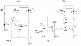
Suppose we now have the diode and you want to perform the adjustments without having access to the procedure. There is one caveat, as always and for this I made two simplified schematics
, for the same diode package. Of course variations are possible function of the actual package type, polarity of supply, etc... Operation is identical, both circuits maintain constant optical power output through the lifetime of the LD (on a given temperature range - reasonable enough). This is based on the fact that when biased in reverse the PD behaves like an constant current generator - its current being a linear function of optical power.
If the monitoring photodiode is in series with the potentiometer (Fig. 1) you must start the adjustment with the pot. at max. value.
Obviously for Fig. 2 the pot must be initially at min. value. You must make sure what type of adjstment you have.
There are other 'little traps' when adjusting the optics in front of a working laser diode. It is a good practice to place it constant current, above the threshold, while doing this because any reflections on the PD might lead the circuit 'to think' that there's not enough current through the LD -> therefore you risk an instant 'supernova'!
Still want to try it? For one I wouldn't! (even having access to some of the equipment - without the adjustment procedure I don't think I can beat the manufacturer)
The best tweak I can recommend though is to keep the LD cool. It won't sound better but the LD might outlive some of us....wait, nobody really wants that!

Attachments
Sorry, been unable to follow up for a few days now...
Ok, this is good info so far. But, we're getting too much data about things that are not going to matter at all in this case.
What we have here is a zinc diecast assembly that the laser diode mounts into. Having dissassembled one already I can see that the is absolutely no mechanical alignment required or possible. The laser diode fits into the hole, a screwed on assembly holds it in place and a flex PCB connects the 3 or 4 pins.
What is not known is the emission point from the reference plane, nor if the monitoring diode is built in or not. A guess as to the power output class would likely be sufficient (I suppose).
The practical adjustment of the laser level and the centering of the focus point via the servo is covered in the service manual for the player - or if you can figure out the trimmer assignments in a generic sense, then for any usual transport. So, that's not too much to worry about. Worst case I smoke a laser by having it set for too much output or not in a linear range and then it doesn't work...
So I suppose that I could possibly "shotgun" the replacement by buying a few likely candidates for the job. The downside to that is that the kapton flex pcb probably won't support an indefinite number of desolder, solder cycles...
Offhand is there a significance to 3 pin vs. 4 pin laser diodes (remember this is a ~10yr old transport now, so the diode is of that vintage)? As in does one always have the built in photodetector, or??
Fwiw, this is a Japanese mfg transport...
_-_-bear
sidiy said:Here is a typical datasheet of a laser diode used in CD-R(W) systems. It has much higher power than a normal LD for playback only.
It answers to some of your questions, I'll try to get back later with some comments. Note the tolerances used for optical alignment (+/- 0.08mm).
I forgot to add a disclaimer: I'm not an LD guru, still ... I had some experience in the past.
This one is visually similar in terms of the package... fwiw.
As I said the thing fits like a glove in a machined hole in a zinc diecast assembly, not much to align there. So, no worries, mate!
_-_-bear
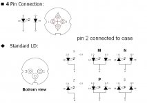
Finally I stumbled on the right stuff... I'll post first a link to datasheet for a Rohm diode (they have a few others on their website). This one is an M-type.
http://www.rohm.com/products/opto_device/laser_diode/laser/rld78mpa1/
Most of times you'll find LDs in the N, P, M configurations.
The 4 pins types have the advantage of connectivity in any configuration, but remember that pin 2 is @ the case for both 3 and 4 pin packages.
It is easy to determine which is the PD (Vdirect= 0.7 - 0.9V) and the LD (Vdirect= 1.6 -2.0V). In circuit they may measure differently - there should be some protective element in antiparallel with the LD.
Edit: any photos of the laser assembly or info on the servo chips (sometimes they tell which types of LD can be controlled...)?
Attachments
another option
might be to state the models of Cd palyers that youdlike the pick up to be replaced ....
you can never know what the international market can do ...
(while trying to repair a nakamichi realy old stuff the nak people said to me that parts like that no longer exist in our company but we can drop a mail to the comapny that originaly constructed them )
result complete sets of idlers for casste players brand new manufactured in Japan in original condition and costed almost nothing ....
give it a try you never know what might be stocked and where /
regards
Sure there are two.
An Onkyo Integra DX-7500
and
An Esoteric (Teac?) transport, have to check the model.
I have no idea how to tap that "international market" without knowing the real ID of the transport mechanism.
Obviously, it makes no sense to spend more than the value of a new unit to buy repair parts.
_-_-bear
An Onkyo Integra DX-7500
and
An Esoteric (Teac?) transport, have to check the model.
I have no idea how to tap that "international market" without knowing the real ID of the transport mechanism.
Obviously, it makes no sense to spend more than the value of a new unit to buy repair parts.
_-_-bear
onkyo some times
used sharp pick ups .... they are still available in greece .... can you post a good picture of the transport ????
meanwhile we have an importer arround that stocks some weird stuff ...i ll drop him a line regarding the model and why not ask him apdf with available replacements ....
keep me posted
regards sakis
- Status
- This old topic is closed. If you want to reopen this topic, contact a moderator using the "Report Post" button.
- Home
- Source & Line
- Digital Source
- CD Transport: Laser Diode Guru?? HELP!!!