Just had to bump this one for new readers
I've spent countless hours optimizing ground planes, regulators and the whole schabang, and this guy goes ahead and makes something so good, yet so simple. Kudos!
Thanks; I call it the "!#*% it" design approach. That means if a project doesn't turn out as planned, I just say "!#*% it".

Seriously though, I think I just get lucky a lot. I wish I knew enough to be able to "optimize ground planes" and such.
Anyone did compared this dac to a TDA1541 dac ?
Sorry, never heard one.
Just had to bump this one for new readers
Ok, so I didn't bump it, I just forgot to look for page 2... Still worth it
Thanks; I call it the "!#*% it" design approach. That means if a project doesn't turn out as planned, I just say "!#*% it".
Seriously though, I think I just get lucky a lot. I wish I knew enough to be able to "optimize ground planes" and such.
Wish I knew that, too... I'm just trying to remember some old tips from pwatts, and winging it from there. With any luck, it'll sound OK. And a Zapfilter from L C Audio takes care of the I/V for me, so I don't have to muck about with that. As long as it sounds better than my old Pioneer CDP with a hopeless powersupply feeding PSU sensitive PCM1702, I'll be almost happy. The "!#*% it" approach doesn't work too well when it takes about a month to have the boards made...
Ok, so I didn't bump it, I just forgot to look for page 2... Still worth it
Does that mean you missed page 4?
The "!#*% it" approach doesn't work too well when it takes about a month to have the boards made...
Yeah, that's why I try to keep my projects simple enough to DIY.
I can't even make acceptable files for a board house to use anyway.
Does that mean you missed page 4?
Nope, I've just set it up to view 50 posts per page. Less clicking that way.
Yeah, that's why I try to keep my projects simple enough to DIY.
Yeah, I did that for a while, but I could never get my PCBs to look good. And I have no idea how to make through-plated holes like vias. How did you do it?
I can't even make acceptable files for a board house to use anyway.
Well, you sure have the skills! Many board houses, like Olimex that I use, accept .brd files straight from Eagle. Just configure a design rule file to fit their standards (10mil minimum tracks etc.) and you're good to go. I dare say it's better for the final design, although it makes it difficult and slow to experiment.
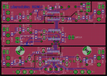
I'm attaching a semi-finished screenshot of my DAC board with SRC. I'll make one without SRC, too, I have a feeling it won't make much difference with a good source like the Lynx AES16. The relay by the left screw switches between 96 and 192 kHz, so I can hook them all up to a simple IR board.
Attachments
Last edited:
And I have no idea how to make through-plated holes like vias. How did you do it?
Real DIY vias require special tools and expensive supplies, and even then you can only make them so small; not worth it IMO.
I just use a small pad with a hole in it and the use a very thin copper wire going through the board. I solder in a length easy enough to work with and then cut off the extra.
Many board houses, like Olimex that I use, accept .brd files straight from Eagle.
Eagle and I agree to disagree with each other. It promised not to cause me any more headaches as long as I promised not to use it. Maybe some day we will learn to get along.
Nice layout by the way!
Yeah, Eagle has a steep learning curve. A whole lot of seemingly illogical and unfamiliar ways of doing things, but if you accept a little headache it might be worth it. I'll see if I can find a tutorial that actually works if you want.
What do you use now?
The problem I was having with eagle is that it's not really designed to make layouts for boards that will be hand made (or maybe I just don't know enough about the program to do so effectively).
I use (abuse) a program called Pad2Pad. It's made by a company that really expects you to have the boards made through them. I use it as a glorified "paint" program though. I don't bother with nets or autorouting; I lay every component, trace, pad, etc. manually. It's really nothing more than a graphic when it's done.
I still use an old student version of AutoCad in the same way. I like it because 1) I (kind-of) know how to use it and 2) it does give you good control over line widths and pad placement. Someday I hope to convert to a PCB program, but previously, I tried a couple of freeware programs and found them more difficult or limited. Next time, I'll give Pad2Pad a try. I have also heard good things about ExpressPCB (same deal - free software intended for ordering boards, but I believe you can also print your own toner etching masks with it)
Last edited:
Hi,
nice little project indeed ;-) Just two little remarks. First the PCM puts out a center current plus minus a signal current. This leads to an voltage offset over the I/V-resistors, which depends on the resistor values. Second, I also prefer the passive I/V conversion via firstclass resistors, but You might think of much smaller values than the 420Ohms in Your schematic. The DAC-outputs of the PCM1794A feature protection diodes which start conducting already slightly above 100mV. The results are quickly increasing distortion values. As long as You stay below 30Ohms the THD-values can be even slightly better than those that BB/TI claim in their Datasheet!
jauu
Calvin
- Status
- This old topic is closed. If you want to reopen this topic, contact a moderator using the "Report Post" button.
- Home
- Source & Line
- Digital Source
- Micro DIR9001 + PCM1794A DAC