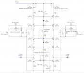
Capacitor multiplier i'm using ( +ve side ).
http://sound.westhost.com/p15_fig3.gif
but i use a single BD679, diode is included in darlington so external is not needed.
http://sound.westhost.com/p15_fig3.gif
but i use a single BD679, diode is included in darlington so external is not needed.
and finaly PSUs:
these have to be adjusted a little in size to fit final MB because aligning the
op-amp sockets to original MB to steal sinal was tricky.
Best way is to align everything in Photoshop using transparancy layers.")
The thingie has been "burning in" since yesterday so i'll recheck calibration this evening and listen to music while contemplating my next project...F3 which is all ready to go in virtual ( CAD ) design!
these have to be adjusted a little in size to fit final MB because aligning the
op-amp sockets to original MB to steal sinal was tricky.
Best way is to align everything in Photoshop using transparancy layers.
The thingie has been "burning in" since yesterday so i'll recheck calibration this evening and listen to music while contemplating my next project...F3 which is all ready to go in virtual ( CAD ) design!
Attachments
Last edited:
Update
Hi guys,
After some initial listening i let the Shanling cook for a week and listened again......
The sound was VERY diferent !!!
It seems the Elkos setlled into a more definite state: the sound is smoother, more organic ...a lot more bass is aparant.
Initially the definition was amazing but i still had the feeling that although bass was there it was only heard at the extremes....like music was super contrasted.
Now though it is in smooth throughout, definition is still there but much more natural.
....it was definitely worth waiting for the cooking !


strange measurements
I built two of these. One is fine, but the other has a problem:
One side measures OK. The other side has wildly fluctuating DC at the output. It moves up and down cyclically, from maybe 4 to 10 volts & then back down & up...
The 2.5vDC at the input is stable on both sides. I'm suspecting 1 or 2 bad 557's. Any ideas?
...A little of topic but very relevant:
Got a Tag Mclaren Av32R192bp at a very nice price to replace an agging AV amp i had and compared the sound with modded shanling........
Gorgeous as the TAG's sound is...it just does not reach the heavenly heights of UGS + modded Shanling.
UGS +Shanling show much better definition, tighter bass.
After reading all the rave reviews it got...and the awards i expected no less but
this just shows how good the modded Shanling is !!!
There is a nice reference for you !
Last edited:
solved
BTW, I discovered on a DAC with diff outputs, you HAVE to use both + and - outputs for each channel. I tried it on the "cheap", using just the + half of each channel on a single board (I don't need balanced outs), but there's just too much noise, sounding like the ocean's roar.
Yep, one resistor was not fully soldered to GND. It now works perfectly.these parts are so cheap , so you can't be wrong even if you change them all .
check solder joints, orientation of parts .......
BTW, I discovered on a DAC with diff outputs, you HAVE to use both + and - outputs for each channel. I tried it on the "cheap", using just the + half of each channel on a single board (I don't need balanced outs), but there's just too much noise, sounding like the ocean's roar.
Hello!
Please if you have the schematic of music Hall 25.2 send me to
mihaidumitrescu2003@hotmail.com
I have Creek Evolution cd player and is the same with Music Hall
Thank You
Please if you have the schematic of music Hall 25.2 send me to
mihaidumitrescu2003@hotmail.com
I have Creek Evolution cd player and is the same with Music Hall
Thank You
I've been very hesitant in posting this time because quite frankly i have some difficulty in describing my latest tests:
Scenario: Sound is gorgeous ..." music ends too soon ! " as my son describes it.
I bypass the coupling Elna Stargets with 10n Siver mica ( did not have polycarbonates ) and:
1 - First impression was that sound had gone "woolly".
2 - Some listening later, conclusion was...bass was tighter, sound was silkier and
highs were all there but more natural, however the sensation that i had lost excitement in the midrange did not disappear.....a week later it still hasn't.
I like the bass a lot, the silky character immensely ....but the music does not end too soon anymore.
I know this is not scientific but my ears couldn't care less, does thid make any sense to you ZM, Manu ?
Anyway Got some pictures for you guys, the boards are ready to be sent to my local shop but before that i would appreciate a review by you guys.
Here they are as is.
Hi CeeVee,
I was glad to see your T80 mod thread after my T80 has been sitting idle for many a year. It looks great and is well built except the sound wasn't exciting even after tube and op amp rolling. Sounds like there is a chance to dust it off and reach more of its potential.
I've been comparing the pcb layout images with the final schematic in post #221 and have questions/possible discrepancies. Note I cannot view the LAY files in #220 on my mac.
1) Pcb shows large C8 while the schematic has no C8. I think C8 is C1 on the schematic.
2) C8 positive terminal connects to Q7/Q5 base on the pcb but Q8/Q9 base on the schematic. Not sure which is correct.
3) Pcb shows 2 components called IVR but can't find them on the schematic.
4) Adjust R1 and R2 to U+/2. Where is U+/2 measured.
5) Can't find R9/R11 on the pcb.
6) R8/R10 in parallel with C3/C4 not labeled on pcb.
7) Dumb question but where is the connection to RCA out.
The last post is kind of old so hope this reaches you.
- Status
- This old topic is closed. If you want to reopen this topic, contact a moderator using the "Report Post" button.
- Home
- Source & Line
- Digital Source
- Upgrade output Shanling CD-S100 MkII