Dear All DIYAudio members:
Anyone have experience on modification on Philips CD950/951 with Tent's XO3, or similar machine, any help and advise would be welcome!
I have a Tent's XO3 Module with reclock option, as the manual of XO3 mentioned, the SPDIF data out should be taken out from Pin 32 of SAA7310GP (http://www.tentlabs.com/Components/XO/assets/XO23mounting.pdf), indicated as HFI of Data Slicer, as other information come across about SAA7310GP, SAA7310GP have no SPDIF out, the SPDIF should be handle by PCF2705, converting I2S from SAA7310 into SPDIF format, and output at Pin 13 of PCF2705.
So where should I extract the SPDIF for re-clcok in of XO3?
and I want to take I2S data out from the CD-951, instead of wiring at Pin 2,3,4 of SAA7310GP, can I extract the I2S from Pin 1,2,3 of PCF2705? Can I do this??
I hope Guido can see this post, I have a hard time to get advise from him.
Thank you for reading.
Hi,
I have a CD940, which I've worked on, and a CD950 for spares. The two models are quite similar. The main difference is the CD940 has more surface mount stuff.
To confirm as I'm working from memory, I haven't actually checked, the PCF2705 is the 14 or 16 pin DIL chip that is fed I2S from the decoder chip and provides the SPDIF output? I think its that one.
Do you want to reclock the I2S on its way to the onboard DAC? If so then this might not be what you want. If you're sniffing off I2S to feed a seperate DAC, then this is the easiest place to do it.
However, if you're reclocking I2S for the onboard DAC, then you'll need to do it after the digital filter, just before the DAC as the filter can add noise and jitter to the I2S signal. Mind you, I've no experience of reclocking a bitstream DAC.
(I sniff off the I2S before it arrives at the SPDIF encoder and use it to feed a seperate DAC, and I've disabled the power to all stages after the decoder, so the player is essentially a transport for me.)
Cheers,
Phil
Dear Phil:
Thanks for your reply, I have 2 aims this time.
1. Re-clock the SPDIF stream by XO3 board for DAC.
I can't really find the SPDIF out pin from SAA7310 datasheet, but Guido manual stated it's Pin 32 of SPDIF, where is correct place to get SPDIF stream for re-clock?
2. Wired the I2S out of the player for external DAC, it's not thing to do with reclock, I feel soldering on DIL chip is more secure than on the SMD chip.
Check the pinouts your self as the SAA7310 has two packages with different pinouts (40pin & 44pin). also Guido relies on emailed info from other techs for some of these pinout and cannot be assumed to be always 100% accurate, I also found one that was wrong a year or so ago.
Cheers George
Cheers George
georgehifi said:Check the pinouts your self as the SAA7310 has two packages with different pinouts (40pin & 44pin). also Guido relies on emailed info from other techs for some of these pinout and cannot be assumed to be always 100% accurate, I also found one that was wrong a year or so ago.
Cheers George
There are SAA7310GP(44 pin QFP) and SAA7310P (40-pin DIL), in Guido manual, no package is indicated, but most SAA7310 found in player is SAA7310GP, so Pin-32 of QFP package called HFI in/out of data slicer, for Pin-32 of DIL package, it's DEEM from Debounce Circuit, none of them looked like SPDIF out, and this player more like using PCF2705 for I2S to SPDIF conversion, and SPDIF out can be found at Pin 13 ( DOBM) of PCF2705, but it's not match with Guido Manual, so I'm not sure which one is correct.
Sorry, I didn't answer your question fully. I nearly did, but editing removed some of the information.
The PCF2705 is ideal for sniffing off both I2S and SPDIF. You'll probably need to lift the leg for the SPDIF output, as you want to reclock and then continue the signal to the output.
The SAA7310 is not used on this player to provide SPDIF output.
The PCF2705 is ideal for sniffing off both I2S and SPDIF. You'll probably need to lift the leg for the SPDIF output, as you want to reclock and then continue the signal to the output.
The SAA7310 is not used on this player to provide SPDIF output.
HiHercules said:Thank you Phil!! I will try to work on PCF2705 tonight!
The PCF puts out SPDIF, I have the pinout at my lab, will check tomorrow
Guido Tent said:
Hi
The PCF puts out SPDIF, I have the pinout at my lab, will check tomorrow
Hi Guido, finally see you but everything were done already. The SPDIF stream was extract from Pin 13 of PCF2705.
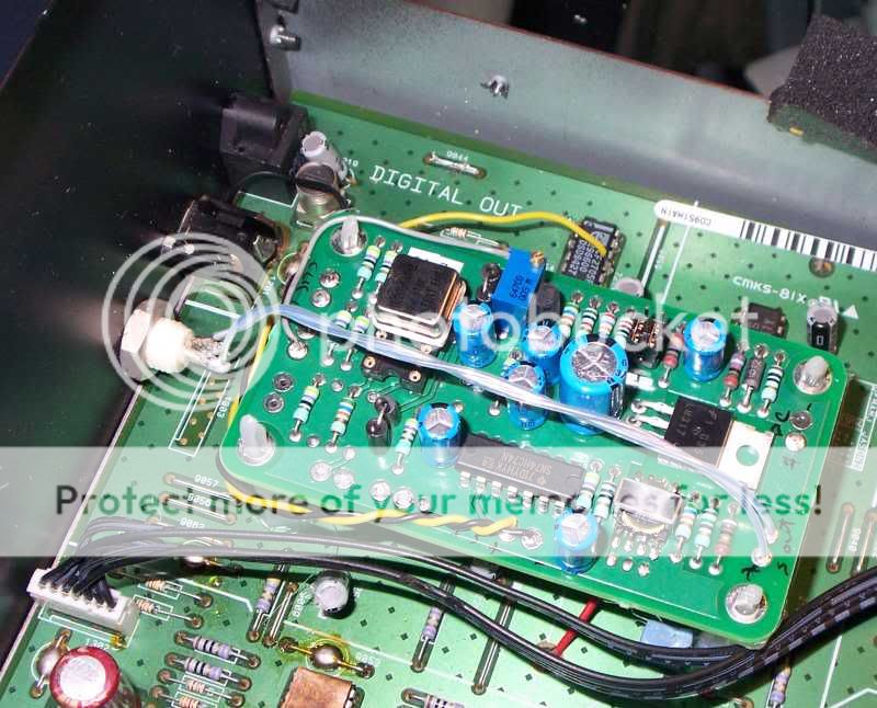
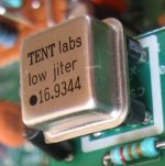
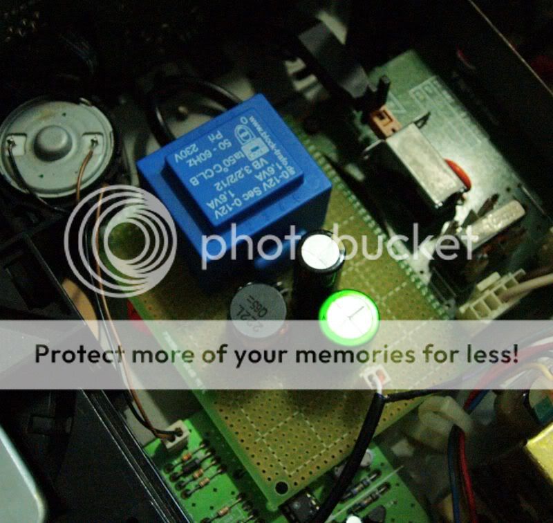
Just one more thing, can you check the XO in this photo is genuine or not, as the wording on it a bit difference from the photo on website
"jiter" instead of "jitter"
"TENT Eng" instead of "TENT ENG"
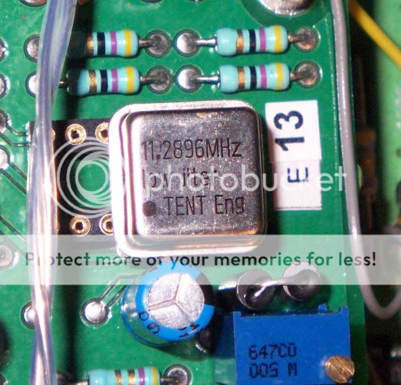
but I still can found 3 blue dot at the bottom of the XO can.
Hercules said:
Hi Guido, finally see you but everything were done already. The SPDIF stream was extract from Pin 13 of PCF2705.
Just one more thing, can you check the XO in this photo is genuine or not, as the wording on it a bit difference from the photo on website
"jiter" instead of "jitter"
"TENT Eng" instead of "TENT ENG"
but I still can found 3 blue dot at the bottom of the XO can.
low jiter, LOL
")
philpoole said:Sorry, I didn't answer your question fully. I nearly did, but editing removed some of the information.
The PCF2705 is ideal for sniffing off both I2S and SPDIF. You'll probably need to lift the leg for the SPDIF output, as you want to reclock and then continue the signal to the output.
The SAA7310 is not used on this player to provide SPDIF output.
I2S comes from SAA7310 and is converted to SPDIF in PCF2705 IC
Hercules said:
Just one more thing, can you check the XO in this photo is genuine or not, as the wording on it a bit difference from the photo on website
"jiter" instead of "jitter"
"TENT Eng" instead of "TENT ENG"
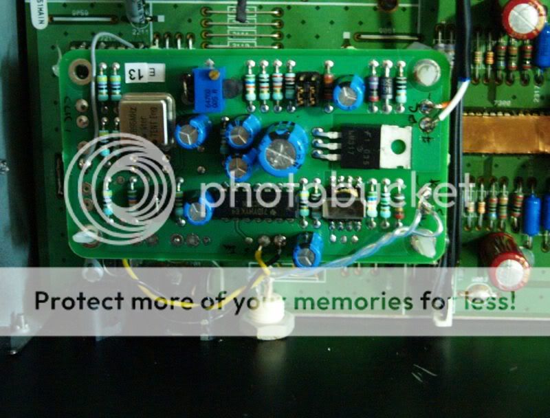
nice work, good to see all is OK. You may want to rotate the board over 180 degrees to shorten all wiring
The text on the oscillaters is a misprint from my Asian manufacturer, and Tent Eng(ineering) was my earlier company when I started this all. The XO's are in production for nearly 10 years now, unchanged that is.
best
thanks for your suggestion, will try to do it next time when I open up the player..
the major difference between XO3 and XO3.2 is shunt regulator only, or more than that??? and divided by two on XO3 is workable or not?? better to use the div. by 2 on XO3 to feed TDA1547 then the SAA7350 div by 2 ?
the major difference between XO3 and XO3.2 is shunt regulator only, or more than that??? and divided by two on XO3 is workable or not?? better to use the div. by 2 on XO3 to feed TDA1547 then the SAA7350 div by 2 ?
Hi Hercules,
Good work!
So, are you just using the CD951 as a transport, or do you ever use its DAC output? If not, then why not disable the power to everything after the 7310? This would make the job of the main regulation easier, and remove now redundant noise from the power rails.
I did this on my CD940, and it was quite easy to do. In fact, I just snipped a few choice safety resistors which are on the power lines to each individual circuit. A careful blob of solder on each snipped leg will bring the circuit back to life - if I'd ever want to do that to a bitstream DAC
By the way, looking at your photos, this will sound a dumb question, where's the rectifier in your new power supply? Is it that small rounded rectangular thing just next to the transformer? Must be I suppose.
Also, the most important questions: how does it sound? Are you happy with the mod? Will you do more?
Cheers,
Phil
- Home
- Source & Line
- Digital Source
- Philips CD-951: Tent Labs XO3 and SPDIF reclock plus I2S out