Peranders,
Again, thanks a lot for your comments and help!
Algar-emi,
I hope Guido Tent should be informed on your results in building the Tube DAC. I think your construction technique is getting more and more refined, and yours is going to be the best example on how to built Guido Tent's Tube DAC project.
Congratulations!
pedro
Hi guys,
My DAC is also finished. If anybody needs PCB artwork I'll be happy to share it. It sound wonderfull! Better than anything I've listened so far (well, maybe not better than AN DAC5).
I tried Svetlana 6N1P, Philips ECG 6922, russian 6N23P, Siemens E88CC... I'm extremely happy with the 6N23P. I tried Audio Note copper foil 0.47uF at the output, but I like Jensen more than Audio Note. Audio Note is more detailed, but Jensen is suited for more music genres.
Guido, thanks for all the help!
Attachments
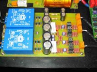
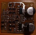
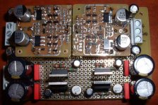
This is SRPP output stage I've been playing with. I'm playing with it mainly because my preamp (Aleph P) has very low input impedance, and SRPP has a lower output impedance and higher gain. I still didn't connect it to the DAC, due to a lack of time, but when I do I'll post my opinion here. It is the clone of Audio Note DAC 4 output stage, so I guess it can sound bad. Here I have Mundorf Supreme Silver/Gold, and I'm planning to hear them in the DAC.
Attachments
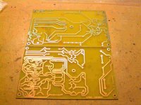
Algar_emi said:Sorry, I bought it directly from Guido Tent. Very nice PCB indeed.
Hi
Made by www.eurocircuits.com
best
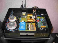
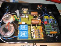
Here is my version of Tube DAC
Hello ALL!
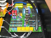
I change circuits of low and high voltage PSU`s and made cascode output stage.
http://www.zeuslab.narod.ru/TubeDAC.htm
AP
Hello ALL!
I change circuits of low and high voltage PSU`s and made cascode output stage.
http://www.zeuslab.narod.ru/TubeDAC.htm
AP
Attachments
Re: Here is my version of Tube DAC
Looks like SRPP to me.
ALP said:Hello ALL!
I change circuits of low and high voltage PSU`s and made cascode output stage.
http://www.zeuslab.narod.ru/TubeDAC.htm
AP
Looks like SRPP to me.
Re: Here is my version of Tube DAC
Neat !
I looked at the schematics. On the analoge output stage, this is an SRPP, not a cascode. We have done extensive lsitening tests, and finally preferred the standard gain stage over the cascode. I think it is a mtter of taste, they are verfy similar. You may want to try the mu stage too, which is a theoretical improvement over the SRPP.
HT design: current sources and shunts, great, I like these !
By the way, the site is quite slow.
cheers
ALP said:Hello ALL!
I change circuits of low and high voltage PSU`s and made cascode output stage.
http://www.zeuslab.narod.ru/TubeDAC.htm
AP
Neat !
I looked at the schematics. On the analoge output stage, this is an SRPP, not a cascode. We have done extensive lsitening tests, and finally preferred the standard gain stage over the cascode. I think it is a mtter of taste, they are verfy similar. You may want to try the mu stage too, which is a theoretical improvement over the SRPP.
HT design: current sources and shunts, great, I like these !
By the way, the site is quite slow.
cheers
Re: Hi Guido
Hi AP
In the linguistic sense I think cascode is still the correct name for an SRPP, but I am not sure. Technically we may be used to the fact that the output is taken from the upper upper side of the whole....
The PCBs where quite an amount of work to do but since many people enjoy them, we are happy after all.
best
ALP said:Thank you for PCB
Yes, of course, output stage is SRPP. You right. It`s my mistake.
AP
Hi AP
In the linguistic sense I think cascode is still the correct name for an SRPP, but I am not sure. Technically we may be used to the fact that the output is taken from the upper upper side of the whole....
The PCBs where quite an amount of work to do but since many people enjoy them, we are happy after all.
best
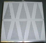
Detail of the top cover plate. After using the dac for some time, it appears that it generate a lot of heat. So I designed a neat pattern of ventilation holes. There is 10 groups of 139 holes  in an arrow pattern. A lot of drilling but it will look good I used AutoCAD to print out the drill pattern.
Bye...
in an arrow pattern. A lot of drilling but it will look good I used AutoCAD to print out the drill pattern.Bye...
Attachments
I'm about to install my version of the Diamond Buffer into ,my Tube DAC. The buffer input is the Tube Output, then a volume control (probably 50K-100K pot) will be after the buffer. So I'll have a variable output with tube sound.
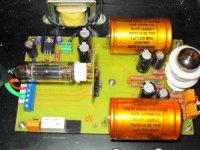
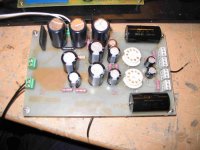
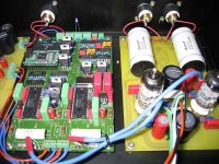
I was not able to get the perfect complimentary transistors for all the buffer transistors (or maybe some needed to be matched). Since the buffer is DC coupled, it caused a small DC offset at the output. To solve this problem I built a daughter PCB where the buffer PCB plugin. The separate LM317/337 regulators supply the buffer at +/-15V. I'm using the +/-25V aux. supply of the DAC supply. If I fine tune the negative supply I can tune out the DC offset. So I installed pot on the LM337 regulators. Now I have an other set of dual mono regulators inside the DAC
Here the image, all point-to-point again.
Attachments
I tested the Diamond buffer and the specs are outstanding. I won't be supprised the sound will be very good indeed
Here the measured specs:
Gain (1V, 1Khz): 1 or 0dB
Distorsion (Ref 1V, 1Khz):
THD(%) IMD(%)
100Hz 0.022 0.020
1Khz 0.015 0.016 (1st harm: -84dB, 2nd: -80dB)
10Khz 0.013 0.017
Freq Response: 10Hz to 20Khz, within 0.1dB
Vmax Tested:
3Vrms, dist: 0.045%
Output DC Offset: Can be adjusted to <1mv dc
Here the measured specs:
Gain (1V, 1Khz): 1 or 0dB
Distorsion (Ref 1V, 1Khz):
THD(%) IMD(%)
100Hz 0.022 0.020
1Khz 0.015 0.016 (1st harm: -84dB, 2nd: -80dB)
10Khz 0.013 0.017
Freq Response: 10Hz to 20Khz, within 0.1dB
Vmax Tested:
3Vrms, dist: 0.045%
Output DC Offset: Can be adjusted to <1mv dc
- Status
- This old topic is closed. If you want to reopen this topic, contact a moderator using the "Report Post" button.
- Home
- Source & Line
- Digital Source
- I started my new Tube DAC