Started the Case
I just started the case at the same time I'm building the ONO case. Check my effort at: http://www.diyaudio.com/forums/showthread.php?s=&postid=263055#post263055
I just started the case at the same time I'm building the ONO case. Check my effort at: http://www.diyaudio.com/forums/showthread.php?s=&postid=263055#post263055
dac' sound
Hola Jesus!
It sounds incredible. Really. It is not that kind of subetivism which depends on everyone perception ...
All the friends that have compare its sound with their equipment agree this DAC sounds marvelous.
Jesus,
Merece la pena!
Una brazo y muchas gracias,
Pedro.
Hola Jesus!
It sounds incredible. Really. It is not that kind of subetivism which depends on everyone perception ...
All the friends that have compare its sound with their equipment agree this DAC sounds marvelous.
Jesus,
Merece la pena!
Una brazo y muchas gracias,
Pedro.
Since last nine month I was asking several diyers on how to solve a problem within my tube dac. I didn't need a preamp (I just use a cd player as a source), so I wanted just a volumen control beetween the tube dac and the power amps.
I tried most of the recommendations I got from some of you: just a vol pot was one of them (but this was not possible, due to impedance's differencies beetwen the tube dac and the power amps).
Finally I found the final solution for a volumen control within Guido's Tube DAC: Peranders "diamond buffer"!
It works PERFECT
Peranders has been totally helpful on teaching me how to adjust his buffer for this particular case (the tube dac).
Just in case some of you has got same problem than I, the "diamond buffer" solution is really a very good one.
Thanks a lot peranders")
I tried most of the recommendations I got from some of you: just a vol pot was one of them (but this was not possible, due to impedance's differencies beetwen the tube dac and the power amps).
Finally I found the final solution for a volumen control within Guido's Tube DAC: Peranders "diamond buffer"!
It works PERFECT
Peranders has been totally helpful on teaching me how to adjust his buffer for this particular case (the tube dac).
Just in case some of you has got same problem than I, the "diamond buffer" solution is really a very good one.
Thanks a lot peranders
After months, I about to complete the actual mounting into the custom casing that I designed and built.
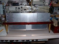
You'll see in the post of the next few days the birth of my Tube DAC. As you probably know, the casing is made of two enclosures mounted on a wood plate suspended on three points.
The top module contains: DAC digital, DC Supplies, Tube HV Supply and Tube Outputs and Op-Amp PCBs. On a central plate will be mounted the two bi-colors leds PLL and HV.
The bottom module contains: AC input and EMI filter with Main Power On Switch, HV and filament transfos and the HV filtration choke. On a central plate will also be mounted the HV On/Off switch and the Main Power On blue Led.
The central plates on both modules are desing to give some distinctive look to the front panel. You'll see what I mean in the next post.
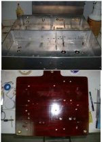
After completion of the case I had to drill all the mounting and wire assy holes. To do so, I had first to figure out what wires to install and where to run them through each modules and PCB.
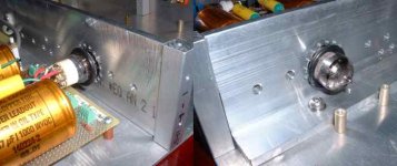
To increase the mechanical strenght of the complete DAC and provide some insulation between the DAC PCB and the HV and Supplies, I install a big piece of 1/4"-2X2" alu channel in the middle of the top module. The piece is bolted between both modules. It is very rigid In addition to this central spine, there 4 others screws, one in each corner that hold the modules together. Finally there is cable clamps installed at strategic location to hold wires.
I had also to drill the wood base. Check the images
To increase the mechanical strenght of the complete DAC and provide some insulation between the DAC PCB and the HV and Supplies, I install a big piece of 1/4"-2X2" alu channel in the middle of the top module. The piece is bolted between both modules. It is very rigid
In addition to this central spine, there 4 others screws, one in each corner that hold the modules together. Finally there is cable clamps installed at strategic location to hold wires. I had also to drill the wood base. Check the images
Attachments
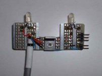
This is what I meant by the central plate. This is the one for the top module. It is done using piece of modem casing, cut and glued together. There is also two mounting screws glued on the back. The images are showing the plate, the plate's rear and the plate mounted on the front of the top module. It will receive the two leds, PLL and HV.
Attachments
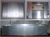
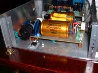
This the completed bottom module. The big toroidal is the HV supply with electrostatic shield. Then, I modified the Tube section to accept 6N1P tube and the filament section of the transfo had not enough current for this tube. So I added an separate Hammond filament transfo. There also a small Hammond choke for the HV CLC filter. They are all mounted just under the HV supply, so the wires are kept to their minimum. The transfos are mounted using a bitumen and neoprene sandwich to reduce vibrations.
On the back we can see the AC input module with EMI filter and Power On switch.
On the front we can see the blue Power-On led and HV switch mounted inside the small 3/8 bar. There is also two small insulated standoffs used to connect both transfo L-N supply lines.
The wire clamps keep the wires nicely routed
Attachments
Nice project!
Question though - who made that 4-layer PCB?
I'm about to order a 4-layer 16x10cm board for a headphone DAC project, and I was thinking of using a 'no touch' Sierra Proto Express board ($102 USD for two, +customs/shipping/etc)
If there's an inexpensive shop north of the border, I'd love to know about it...
Finally some sound
After months of delays, I finally start to listen to some nice music coming from my Super DAC
I just completed the interconnection of all the PCB and the sound is superb.
The only part missing is the solid stage amp section. I'm planning to rework the class-A Op-amp as my NOS 1545 DAC using FET's biais. This is not really a big miss because I included mainly the solid state section to demonstrate the much superior tube section sound in the first place, and to do some experiment.
I also included the space to mount two small SMD diamond buffer pcb's to be able to install a volume control and be able to use the DAC without preamp if I wish. See this site for the detail on the diamond buffer. Thanks Pedro for this info:
http://home.swipnet.se/~w-50719/hifi/qrv05/index.html
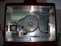
I had to rework the tube section to have the tube mounted horizontally, so I can close the top cover. Here some details of the tube section assy. You can see the rectifier tube with a small heatsink on top and the filament 6.3V LM317 regulator mounted directly on the frame for heat dissipation.
The amp tube pass trought the central metal cross member that then act as a heatsink, see next post...
After months of delays, I finally start to listen to some nice music coming from my Super DAC
I just completed the interconnection of all the PCB and the sound is superb.
The only part missing is the solid stage amp section. I'm planning to rework the class-A Op-amp as my NOS 1545 DAC using FET's biais. This is not really a big miss because I included mainly the solid state section to demonstrate the much superior tube section sound in the first place, and to do some experiment.
I also included the space to mount two small SMD diamond buffer pcb's to be able to install a volume control and be able to use the DAC without preamp if I wish. See this site for the detail on the diamond buffer. Thanks Pedro for this info:
http://home.swipnet.se/~w-50719/hifi/qrv05/index.html
I had to rework the tube section to have the tube mounted horizontally, so I can close the top cover. Here some details of the tube section assy. You can see the rectifier tube with a small heatsink on top and the filament 6.3V LM317 regulator mounted directly on the frame for heat dissipation.
The amp tube pass trought the central metal cross member that then act as a heatsink, see next post...
Attachments

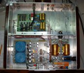
And the complete top view without the op-amp section, and the future options of the diamond buffers and volume pot.
Remark the short lenght of real and low loss 75 ohms coax coming from the back routing the digital signal. It connects to a real 75 ohms panel mount coax union adapter.
Remark the short lenght of real and low loss 75 ohms coax coming from the back routing the digital signal. It connects to a real 75 ohms panel mount coax union adapter.
Attachments
That's only the normal I....pedro said:Peranders has been totally helpful on teaching me how to adjust his buffer for this particular case (the tube dac).
Just in case some of you has got same problem than I, the "diamond buffer" solution is really a very good one.
Thanks a lot peranders
 .... Thanks!
From what I remember you have been the most difficult case in interfacing the buffer right. I'm glad we worked it out finally. Tube outputs are a bit special becasue their rather high output impedance.
- Status
- This old topic is closed. If you want to reopen this topic, contact a moderator using the "Report Post" button.
- Home
- Source & Line
- Digital Source
- I started my new Tube DAC