I am still having trouble trying to get the PS board to work ! I have found a CT 24 +24vac tranny and connected it as detailed in Audio1st's post. I cannot get it to power without the light bulb glowing very brightly and no DC output !!!!
http://www.diyaudio.com/forums/attachment.php?s=&postid=1494452&stamp=1209233090
I have severed the connection at ground and connected the CT at that point ? What am I doing wrong ?
http://www.diyaudio.com/forums/attachment.php?s=&postid=1494452&stamp=1209233090
I have severed the connection at ground and connected the CT at that point ? What am I doing wrong ?
Guan: The black lead should goto the minus, and the red lead to the plus. The plus should be marked on the top and bottom of the board.
Puffin: 2 x 24v volts is wayyyyyy too much. 2 x 10, or 2 x 12V is the way to go. You may have damaged the regulator unless your heatsink is HUGE... The centre tap should go directly to the negative leg of the first cap (the cap BEFORE the regulator). The other two leads go to both AC holes on the board. Make sure you add the wire link from the diode board to the main board as detailed around page 17...
Check the diodes (MSR860?) are oriented correctly - at the risk of laboring a point, take a CLOSE look at Okap's PDF for this. The white lines should indicate where the diodes are placed. I used two with my 2 x 12V transformer.
- John
Michael Percy also still has good stocks of Black Gate capacitors, and will ship pretty much worldwide. (He's a bit busy right now, but I got my latest order this week in less than 4 days.)
I used a combination of standard and PK (miniature) grade caps in mine. I have tried a few others here and there and it seems like the BG are usually superior. The PK seem to fit fairly well, the standard size a bit less so..
RCEZ32 Specific (Might apply to RCEZ31 mech as well):
In the RCEZ32 board set there is a row of 4 capacitors directly under the rack and unless the caps (std BG) are mounted snug against the board there is a possibility that the limit switch operator (a little plastic post) will hit them. There is something like 11-12mm between the plastic "operator" post and the pcb. Bending them over is not such a good option either as this interferes with reinserting the ribbon from the mechanism once you have completed the mods.
johnm said:Guan: The black lead should goto the minus, and the red lead to the plus. The plus should be marked on the top and bottom of the board.
Puffin: 2 x 24v volts is wayyyyyy too much. 2 x 10, or 2 x 12V is the way to go. You may have damaged the regulator unless your heatsink is HUGE... The centre tap should go directly to the negative leg of the first cap (the cap BEFORE the regulator). The other two leads go to both AC holes on the board. Make sure you add the wire link from the diode board to the main board as detailed around page 17...
Check the diodes (MSR860?) are oriented correctly - at the risk of laboring a point, take a CLOSE look at Okap's PDF for this. The white lines should indicate where the diodes are placed. I used two with my 2 x 12V transformer.
- John
I agree, this will put the raw dc voltage right on the hairy edge of regulator failure or worse depending on who made the regulator. Parts made by National, Fairchild, and Rohm all have max input ratings of 35V, with high line and a 24V winding you will easily exceed this.
John & Kevin. I am not normally this stupid and have made many succesful power supplies. It seems I cooked the reg with the 24v ! (no pops, no smoke - just a "silent and deadly", me thinks)
Why I thought 24v each side was right I'll never know.
I substituted a higher voltage reg (using a dual 12v tranny) and it works, but is of course too high DC.
Off to Maplin's tommorrow for some 7808's !
Why I thought 24v each side was right I'll never know.
I substituted a higher voltage reg (using a dual 12v tranny) and it works, but is of course too high DC.
Off to Maplin's tommorrow for some 7808's !
We've all been there mate - anyway at least nothing irreplaceable was damaged so it's all good ") You can always use the stock supply and board while you wait as well.
You can always use the stock supply and board while you wait as well.
Do Maplins do 7808's? I'm sure they didn't have any last time I looked - could be wrong though. I had to get mine from Peter, and also RS.
You can always use the stock supply and board while you wait as well.Do Maplins do 7808's? I'm sure they didn't have any last time I looked - could be wrong though. I had to get mine from Peter, and also RS.
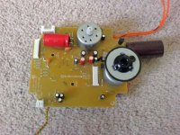
Update on my JVC mods: once AGAIN, I have replaced C906! From the paper in oil which I initially raved about, BACK to the original electrolytic 0.1uF / 50V. For my (or my ears!) there's just something right about this part in C906. I've stopped trying to rebuilt everything with audiophile parts (just because I may have the parts handy) and trusted my ears instead on this occasion. Have a theory that perhaps the laser is adjusted (there's an adjustment pot visable near the laser) with this part in place, which would take into account the EXACT value of the part (in my case 0.14 ohms). Perhaps when replacing C906 the 'ideal' isn't met any longer. Whatever the reason I'm sticking with this part now, and the original clock. To me at least, they are part of the 'magic' of the original sound. Someone mentioned earlier in the thread that with th estock JVC you can almost hear the tautness of a drum when hit - no overhang etc. It was this facet of the performance I seemed to loose with 'upgrading' the clock and C906. I've got those back again now, with all the benefits of a much improved power supply. I couldn't be happier with it now
Today I replaced the 100uF Silmic I had in position C939 with 47uF Black Gate N type.
I also replaced C953 from a Panasonic FM 220uF to - again - a Black Gate 47uF N type.
As far as the board is concerned that's it for the mods now. I'm also tired of taking the thing apart
Time to start experimenting with supports, chassis etc etc etc
Attachments
Puffin said:Who said BG's take weeks to come on song !
Have been using mine as standard with a BNC out (no resistors)
Made it 75ohms last night, not bad, less glare and grain.
Having got my bits from Peter earlier in the week (with the caveat of "you don't neccessarily need them all") I thought I would attack it.
Removed R1 - R5
Substituted, E1, 10uf and E5 47uf for the BG's.
Well, bugger me, how good is that (30 mins on them at present) ! If they get any better then it's a bonus.
Now I've got to tread carefully as to any other substitute. I am going to leave the crystal as standard at present.
John. I have the rest of the stuff Peter sent me. Which other parts would you substitute ? I intend to leave the crystal as standard.
Everything I've done is here Puffin, but here it is in one place:
C934 - Black Gate N 4.7uF / 50V
C953 - Black Gate N 47uF / 50V
C929 - Black Gate N 4.7uF / 50V
C906 - Stick with original part.
C916 - Black Gate N 47uF / 50V
C939 - Black Gate N 47uF / 50V
C952 - Elna Silmic ARS 470uF / 63V
X901 - Stick with original.
Hope thats of help Puffin.
- J
C934 - Black Gate N 4.7uF / 50V
C953 - Black Gate N 47uF / 50V
C929 - Black Gate N 4.7uF / 50V
C906 - Stick with original part.
C916 - Black Gate N 47uF / 50V
C939 - Black Gate N 47uF / 50V
C952 - Elna Silmic ARS 470uF / 63V
X901 - Stick with original.
Hope thats of help Puffin.
- J
Yep exactly what I found - I liked the detail and immediacy of the Auricap, and - initially - loved the rich sound I got from the Jensen paper in oil.
However with the original part the sound just seems to 'relax' somehow and find it's own groove - its free to live and breathe! At the end of the day it just makes music sound real to me in a way the others didn't. Ditto for the crystal as well, at least with my ears and equipment
However with the original part the sound just seems to 'relax' somehow and find it's own groove - its free to live and breathe! At the end of the day it just makes music sound real to me in a way the others didn't. Ditto for the crystal as well, at least with my ears and equipment
Peter. Thank you very much for your kind offer, but unless I draw a complete blank here in the U.K I would not ask you to send one all that way.
I am currently using a variable dc PS, and found that at 8v the CD didn't read properly. At 8.5v it is fine. So what about a 7809 ? Would it be o.k ?
I am currently using a variable dc PS, and found that at 8v the CD didn't read properly. At 8.5v it is fine. So what about a 7809 ? Would it be o.k ?
Puffin said:John & Kevin. I am not normally this stupid and have made many succesful power supplies. It seems I cooked the reg with the 24v ! (no pops, no smoke - just a "silent and deadly", me thinks)
Why I thought 24v each side was right I'll never know.
I substituted a higher voltage reg (using a dual 12v tranny) and it works, but is of course too high DC.
Off to Maplin's tommorrow for some 7808's !
Lots of people still make the 7808, should not be too difficult to find someone who sells it besides Maplin... (Read your not so great experience with "Craplin" a couple of posts back.)
Don't feel too bad, hopefully you have read how I destroyed the micro-controller in my first board set.. No one could have been much stupider than me.

- Home
- Source & Line
- Digital Source
- Finally, an affordable CD Transport: the Shigaclone story