Dreaming is half the fun in my book and I do think there is a lot of mileage in finding what you like and sticking with it.
With pictures, when you get the reply box at the bottom, You can go advanced. you will find further down that page an additional box that gives "additional Options". One of these is "Attach files" with the title "Manage Attachments" and gives a series of boxes to allow images to be entered. One box per image. It allows you to search your computer for your image much like you can for emails. Hope that helps?
Regards
Trevor L
Last edited:
Ray hi,
All my reading so far of this thread, (currently up to page 240), has indicated that there are two JVC models only that are suitable for the mods presented here. Those models are the RC-EZ31 and RC-EZ51. (I just received my EZ51 from Amazon UK). It is possible to use the EZ-32 but the guys that did so were a bit out on their own. Some replys also mentioned another JVC compact sterio as having similar components but after 240 pages of this I am a bit fuzzy as to where! Other players will use different chips with additional features that make the mods detailed here problematic. The beauty of this boombox apparently is its relative simplicity.
Regards
Trevor L
Not so much the transport itself even, just the PCB that sits under it. The transport is available separately. In the UK Ebay has them, (it's actually a Sanyo drive), just do a search on SF-P101N and a load come up, cost about £8. If anyone can come up with the board or a direct equivalent, you're in business. The display is basic and only really consists of a wiring job to the display itself and the remote sensor.
Trichord no 4 was done as was Kwak Clock and one DIY off ebay and others. This guy "Erik van Voorst" did an amazing build with top class components, (cost like 3000 Euro's or more in the end). The crystal alone was replaced with Citizen 300-8441 oscillator with mixed results, some returned to original, some loved it. Best upgrades seem to have been the PSU, the circuit Mods as per the .pdf, and the originally suggested mounting configuration with sollid mounting on metal and a heavy wood base. The Peter Daniels NOS DAC has also resulted in a noticeable benefit, others also.
Try some searches on this thread and you will come up with alternatives others have tried. Not all made an improvement...
Try some searches on this thread and you will come up with alternatives others have tried. Not all made an improvement...
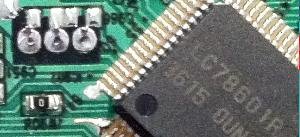
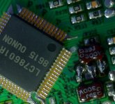
I have come across a very interesting substitute. It is a Lenoxx Sound CD-101.
The chip set is:
LA9250
LC78602y
LA6541
Also, it already doesn't have the choke and filter cap. It operates on eight volts and is whisper quiet. I think I will give it a listen as is tonight to see what it sounds like. I have two of these and they are the same model number and have different transports inside. One has a Sony chip set and then the other has this chip set. Any thoughts on this from those who know much more about such things?
CHEAP BUT EFFICIENT CLOCK UPGRADE
@all
Hello,
Sorry if this mod has ever been mentioned by someone else but this thread is long
I am not sure I remember everything...
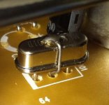
I've been very disappointed trying to replace the stock ceramic oscillator with a super clock or even a simple cristal...
In theory a cristal is much better than a costless ceramic oscillator...
But a oscillator has 3 pin and a crystal only 2.
I measured the integrated capacitors between the central point of the oscillator and with the 2 output legs : exactly 39 pF.
If you look at the pcb there are 2 unused places for SMD capacitors close to the oscillator...
I was not able to find quality SMD 39pF capacitor so I ordered 2 regular Silver Mica (5%).
I soldered and extra wire on the top of the new cristal (regular low profile with metal case) and replaced the stock one.
I soldered the silver mica capacitors on the solder side.
To me the result is much much better than with the regular oscillator !
Thats just my two cents... please experiment.
Cheers !
@all
Hello,
Sorry if this mod has ever been mentioned by someone else but this thread is long
I am not sure I remember everything...
I've been very disappointed trying to replace the stock ceramic oscillator with a super clock or even a simple cristal...
In theory a cristal is much better than a costless ceramic oscillator...
But a oscillator has 3 pin and a crystal only 2.
I measured the integrated capacitors between the central point of the oscillator and with the 2 output legs : exactly 39 pF.
If you look at the pcb there are 2 unused places for SMD capacitors close to the oscillator...
I was not able to find quality SMD 39pF capacitor so I ordered 2 regular Silver Mica (5%).
I soldered and extra wire on the top of the new cristal (regular low profile with metal case) and replaced the stock one.
I soldered the silver mica capacitors on the solder side.
To me the result is much much better than with the regular oscillator !
Thats just my two cents... please experiment.
Cheers !
Attachments
Last edited:
I soldered and extra wire on the top of the new cristal
what exactly do you mean by "new wire on the top of the new cristal"?
Hi !
I use this one http://item.mobileweb.ebay.fr/viewitem?itemId=400231819515
This is standard cristal.
I simply used the central pin ground connection
of the stock oscillator.
Rgds
I use this one http://item.mobileweb.ebay.fr/viewitem?itemId=400231819515
This is standard cristal.
I simply used the central pin ground connection
of the stock oscillator.
Rgds
Last edited:
I think Peter mentioned something much earlier in the thread about using a couple of twists of wire to add a little capacitance....
So just to be clear.... you soldered one side of each cap to the crystal body, and the other side to the 2 outside pads on the board?
Fran
So just to be clear.... you soldered one side of each cap to the crystal body, and the other side to the 2 outside pads on the board?
Fran
 !
!
Hi, apoligies if this has been answered but it's a long thread and I've read most of it and Peters condensed version.
I have the parts from an EZ51 which has a different display pcb.
There are 3 grey wires and 1 orange entering a plug marked led led sync sync.
with a legend saying it goes to the main board.
Could anyone please say what I do to these wires, if anything")
I don't need to cut down the board.

I have the parts from an EZ51 which has a different display pcb.
There are 3 grey wires and 1 orange entering a plug marked led led sync sync.
with a legend saying it goes to the main board.
Could anyone please say what I do to these wires, if anything
I don't need to cut down the board.
Hi J Baldam.
It looks just as mine.
I cut the 2 rightmost ones down and the grey nmbr2 goes thru a pot to tha lowest connectorpin on the flatcable connector. I took the orange one to the left/most downwards connector of SW706 ( the most right/most downwards switch (repeat?))
Brgds
It looks just as mine.
I cut the 2 rightmost ones down and the grey nmbr2 goes thru a pot to tha lowest connectorpin on the flatcable connector. I took the orange one to the left/most downwards connector of SW706 ( the most right/most downwards switch (repeat?))
Brgds
Hi, thanks for the reply,
Right I discard the 2 right grey wires.
I connect the remaining grey to the lowest pin on the outside connector row.
The orange goes to the repeat switch.
Think I've got it but the grey through a pot
and could you please tell me why this has to be done
cheers
Right I discard the 2 right grey wires.
I connect the remaining grey to the lowest pin on the outside connector row.
The orange goes to the repeat switch.
Think I've got it but the grey through a pot
and could you please tell me why this has to be done
cheers
- Home
- Source & Line
- Digital Source
- Finally, an affordable CD Transport: the Shigaclone story