"Take the mechanism off the bottom controller board"
Separate the controller board from the upper plate that holds the motors and laser sled. That way there are fewer vibrations reaching the electronics.
"Remove output resistors and use RF attenuators instead"
I use RF attenuators to drop the signal from TTL to consumer. They kill reflections in the cabling which can cause mistiming of the spdif signal - jitter. In every case where I've used them so far, the sound has improved, cleaner bass and treble.
See my original post here:
RF attenuators
Fran
Hi Peter,
would you be so kind and shortly give an abstract of your latest recommen-
ded modifications?
I presented a simple approach here: http://www.diyaudio.com/forums/audio-sector/160373-cd-transport.html This is still most rewarding solution when you consider time and parts vs results. I use one of those transports in my system and can't complain at all. This is also the essence of Shigaclone transport: pushing the envelope of simplicity
")
You can improve further by adding dedicated 5V regulator, adding more transformers to PS, more caps, changing some other caps etc. My recent experiences have been described here:
http://www.diyaudio.com/forums/digi...ansport-shigaclone-story-219.html#post2494104
http://www.diyaudio.com/forums/digi...ansport-shigaclone-story-220.html#post2495131
hello all,
first, Peter Daniel, thank you very much for starting this thread. I have fun a lot.
In this trhead on page 128, #1273, Slawney make a few statements, he wrote " One word of caution to those pursuing a
multiple reg approach, however, the timing of the start up of different regs must be properly adjusted to avoid latch up because of an absent clock signal or such. Sympton will be no toc or a servo spinning out of control upon start up."
So, is there anybody that can explain whats this mean, and how to solve this problem?
Woood09
Hello all
Peter Daniel, thank you very much for starting this thread.
On page 128 of this thread, #1273, Slawney make this statemend,
"One word of caution to those pursuing a multiple reg approach,
however the timing of the start up of different regs must be properly adjusted to avoid latch up because of an absent clock
signal or such. Sympton will be no toc or a servo spinning out
of control upon start up."
Is there anybody that can explain this statement, and can solve
this problem?
Woood09
Latch-up in a chip basically means that it "freezes" in a certain state, waiting for a signal input that never came.
If all the chips do not receive the +5V AT THE SAME TIME, some chips could be on and end up waiting/freezing for an input while others are still turning on.
This could permanently damage the transport.
And the solution is simple: Feed the chips off the same 5V reg.
If all the chips do not receive the +5V AT THE SAME TIME, some chips could be on and end up waiting/freezing for an input while others are still turning on.
This could permanently damage the transport.
And the solution is simple: Feed the chips off the same 5V reg.
Hello all
Peter Daniel, thank you very much for starting this thread.
On page 128 of this thread, #1273, Slawney make this statemend,
"One word of caution to those pursuing a multiple reg approach,
however the timing of the start up of different regs must be properly adjusted to avoid latch up because of an absent clock
signal or such. Sympton will be no toc or a servo spinning out
of control upon start up."
Is there anybody that can explain this statement, and can solve
this problem?
Woood09
I am pretty sure that pushing the tray switch resets the chip and forces it to read the TOC
Cable too!!!
Same guy also has extra long film cable.
FLEXIBLE CONNECTION FLAT CABLE 15P FOR SF-P101N (15PIN) on eBay (end time 21-Apr-11 01:00:01 BST)
Same guy also has extra long film cable.
FLEXIBLE CONNECTION FLAT CABLE 15P FOR SF-P101N (15PIN) on eBay (end time 21-Apr-11 01:00:01 BST)
separate regs
Hello Dr. H, thanks for your reaction. imo, Slawney suggested that he use separate regs, and his transport works properly. Thus he solved the problem with different regs.
Hello Hotiron, To switch the doorswitch was not working, It seems that the transport was "pissed", it stil didnt work. When return to a single power supply, everything was ok.
Stil I like to know, is it possible to use different regs?
Why? It will increase the sound.
Slawney?
Regards,
Woood09
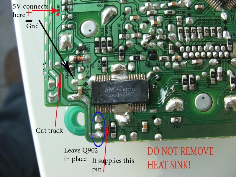
Yes, it is possible ti use separate regulators and if you connect them as in a picture here: http://www.diyaudio.com/forums/atta...ble-cd-transport-shigaclone-story-track5v.jpg everything should work fine.
I also recall that at one time my CD was spinning out of control after powering the transport, resetting TOC brought things to normal.
I keep it on permanently and don't experience any anomalies.
I also recall that at one time my CD was spinning out of control after powering the transport, resetting TOC brought things to normal.
I keep it on permanently and don't experience any anomalies.
It makes lots of sense to feed the driver and digital chips with separate regs
as the motor drivers inject loads of noise back towards the DSPs.
The only way this baby can latch up, is if there is no clock present.
eg: 8v supply to driver chip (supplying 4 motors,Focus,Tracking,Spindle and Sled) And 5V supplying the digital side.
The driver chip as most of you know, has an on chip 5V reg which supplies the whole board. YUK!
FWIW, I am using a separate 8V supply and 5V supply (ALW reg) connected as suggested by Peter's recent pic
http://www.diyaudio.com/forums/attac...ry-track5v.jpg
Sounds cleaner than simply using just the 8V supply.
I guess the question remains as to whether there is a sonic benefit in splitting the 5V supply even further and giving each DSP chip that needs 5V a seperate 5V reg. Possibly the benefit will be minimal.
I'd also be very interetsed in the VREF pin on the driver chip. Is that a high impedance node? If it is, there is a JohnW VREF external circuit that could do great magic here!
http://www.diyaudio.com/forums/digital-source/25213-capcitor-type-vref.html?perpage=10&pagenumber=3
Hello
Peter Daniel, Hotiron, Dr, H, The picture have I see before. I'am some careful, because I have 2 jvc pcb destroyed, You know,
connect and disconnect, solder and desolder, tracks release from the bord, some can repair with a wire jumper, but not all the mistakes. Still I have some confusion about transistor Q902.
I have read some let him stay, some delete. I believe delete Q902,
because the 5v reg in the driver chip is not a good one. But what to do wiht the reg output if I delete Q902?
regards
Woood09
hi BMW850,
First do make sure that disk will work in another machine,Hold it up to the light, if you can see any scratches on it ,get a black magic marker and cover them on the label side,
then here's a starting place Notes on the Troubleshooting and Repair of Compact Disc Players and CDROM Drives
good luck !
First do make sure that disk will work in another machine,Hold it up to the light, if you can see any scratches on it ,get a black magic marker and cover them on the label side,
then here's a starting place Notes on the Troubleshooting and Repair of Compact Disc Players and CDROM Drives
good luck !
- Home
- Source & Line
- Digital Source
- Finally, an affordable CD Transport: the Shigaclone story