3A diodes are fine as replacements for 1A types.
The size of heatsink needed is determined by the load current and voltage 'lost' across the regulator. So that means the rating of the regulator has no impact on temperature, the 1A device and the 2A one will both run at the same temperature for a given load current.
The size of heatsink needed is determined by the load current and voltage 'lost' across the regulator. So that means the rating of the regulator has no impact on temperature, the 1A device and the 2A one will both run at the same temperature for a given load current.
Right, thanks for your reply!
I’m going to place “oversized” components, then.
If I want to check and (re)set the bias levels on the power amplifiers, where would I measure the offset current? Across the emitter resistors?
The idle current-offset is usually expressed as a voltage, so I figured it’s measured across the emitter resistor.
Since I don’t know if and how well the transistor pairs are matched, what would be a safe voltage to set? About 800mV?
800mv sounds way to high ")
Typically you are measuring across a resistor in the 0.1 to 0.47 ohm range and calculating bias current from the dropped voltage.
The recommended current could be anywhere from as low as around 10 milliamps up to 100ma, it all depends on the type of output stage as all are different. Also the theoretical correct bias for a given configuration may generate to much heat and so the manufacturer deliberately under biases. That is common on multi channel amps where commercial pressures mean the heatsinks would need to be much bigger.
So the answer is to follow the service manual procedure or leave it alone. There is no reason for it to change in use.
Yeah, massive typo. Thanks for your reply!800mv sounds way to high
Typically you are measuring across a resistor in the 0.1 to 0.47 ohm range and calculating bias current from the dropped voltage.
The recommended current could be anywhere from as low as around 10 milliamps up to 100ma, it all depends on the type of output stage as all are different. Also the theoretical correct bias for a given configuration may generate to much heat and so the manufacturer deliberately under biases. That is common on multi channel amps where commercial pressures mean the heatsinks would need to be much bigger.
So the answer is to follow the service manual procedure or leave it alone. There is no reason for it to change in use.
I thought there wasn't any info in the service manual, but it turns out there is. I just looked for it in the wrong places. Depending on the channel, the bias voltage across the emitter resistor should be anywhere between 6 and 10mV:
FL/FR/C: 10mV +/- 2mV
SL/SR/BSL/BSR: 6mV +/- 1,5mV
I have the impression the machine is running a little warm. So I suppose I'll check if it's in the right range. If it ain't broke, I won't try to fix it.
Last edited:
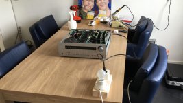
Okay, everything is put back together. I’ve connected the amp to mains through a 60W light bulb safety. The lamp lights up, at which time the amp clicks several times, but doesn’t start up. Then the bulb goes out. This cycle repeats. Could it be the bulb drains too much voltage?
I think secudairy circuits, such as the main pcb, which in turn powers the rest of the amp, don’t start up after the main psu has started up normally. Is that thought correct?
At this time I’m not confident enough to connect the amp directly to mains power.
I think secudairy circuits, such as the main pcb, which in turn powers the rest of the amp, don’t start up after the main psu has started up normally. Is that thought correct?
At this time I’m not confident enough to connect the amp directly to mains power.
Last edited:
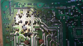
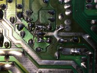
There was quite some damage to the pcb. The L78M56 has come loose altogether. I fixed that by extending it’s legs, and bending those to connect with the legs of the new C146/147, in order to maintain some mechanical stability.
Besides that, it looks like someone else has done a similar repair in the past. There is solder work on the pcb that was done after manufacturing. Most diodes are non-factory originals (higher current rating). So to minimize the risk of further damage to the pcb, I left the diodes alone and only replaced most power filter caps (including those in the main psu) and five voltage regulators.
Now, I hope it will start up normally. At the moment, behind a light bulb safety, it won’t.
Attachments
Last edited:
Fair enough. I was afraid of that. Since conventional bulbs are banned here and I don’t have any other, I’m afraid I’ll either have to risk frying everything, or leave it at this and leave testing to some one else...
There is another option, perhaps. Call my parts supplier (a store) and see if they’re willing to lend their test bench to me...
There is another option, perhaps. Call my parts supplier (a store) and see if they’re willing to lend their test bench to me...
Succes!! The amp fired up in one go and it seems to work like it should. Ok, the volume enocoder is badly in need of replacement and the dsp card seems to be fried (digital modes result in heavily distorted sound), but other than that: it starts up normally and the direct mode sounds pretty good!
Does anyone have any experience in repairing the dsp board? Or is that impossible to do without any serious measurement gear (I have literally one multimeter and that’s it).
Does anyone have any experience in repairing the dsp board? Or is that impossible to do without any serious measurement gear (I have literally one multimeter and that’s it).
It is always worth checking as much as you realistically can such as supplies. Beyond that its a case of looking at the circuit at trying to figure out what any expected voltages around any analogue sections should be and confirming they are correct. Look for physically suspect parts, SMD electrolytic caps that might have leaked and so on.
- Status
- This old topic is closed. If you want to reopen this topic, contact a moderator using the "Report Post" button.
- Home
- Source & Line
- Digital Source
- Arcam AVR300 diode replacement?