I have read so many posts about how good it is to slave the transport to the DAC.
Yet I have searched and there is lot of hot air about how to do it but not one dam circuit diagram.
I think it is a hoax. I contend it has never been done outside of a few expensive commercial products.
DIY, no it hasn't been done.
This is supposed to be the proven way to reduce jitter. Why hasn't then been a shared project on how to do it.
Consider a traveller who wants to get from A to B. Said traveller has a number of options.
1. Traveller sits around waiting to be handed a map and GPS receiver
complete with waypoints.
2. Traveller learns to read a map and understand grid references and
is now pretty much independent.
3. Traveller gets a map, acquires some idea of present location relative
to destination and seeks help where necessary.
rfbrw said:Consider a traveller who wants to get from A to B. Said traveller has a number of options.
1. Traveller sits around waiting to be handed a map and GPS receiver
complete with waypoints.
2. Traveller learns to read a map and understand grid references and
is now pretty much independent.
3. Traveller gets a map, acquires some idea of present location relative
to destination and seeks help where necessary.
god... I love the scarcasm on these forums (!)

Regal, just wait until someone who's got the inclination & good heart to help comes along....I would help you gladly, but my knowledge in Digital electronics just doesn't go that far (sorry).
If you look around on the digital section of the forum, you'll see many peeps that have a wealth of knowledge. You could contact them directly and see if they want to contribute to the thread you started...
All the best !!
-Andy-
That's the way to do it, Mr Punch!
Indeed one could just wait for one of the Tefal boffins to disdainfully sweep a few crumbs of knowledge one's way.
Alternatively, one could take the replies already received in one's previous threads and seek to expand on the information already received.
Another option would be to use the search function. That way one would find out that this is not an uncommon topic and the various options have been covered once or twice. One would learn about wordclock, Superclock, error signals and DDS not to mention some very practical information about the implentation of clock syncing between the Isodac and the Discmagic giving one an insight into the task at hand and that one could ultimately adapt said information to suit one's needs.
Then again one could just spit the dummy.
NjoyTHEMUSIC said:
Regal, just wait
Indeed one could just wait for one of the Tefal boffins to disdainfully sweep a few crumbs of knowledge one's way.
Alternatively, one could take the replies already received in one's previous threads and seek to expand on the information already received.
Another option would be to use the search function. That way one would find out that this is not an uncommon topic and the various options have been covered once or twice. One would learn about wordclock, Superclock, error signals and DDS not to mention some very practical information about the implentation of clock syncing between the Isodac and the Discmagic giving one an insight into the task at hand and that one could ultimately adapt said information to suit one's needs.
Then again one could just spit the dummy.
Re: Aren't slaves banned now ??!!
What else would a Tafiosi look like ?
NjoyTHEMUSIC said:
Hey rfbrw, how did you know that I have a receiding hairline ???
What else would a Tafiosi look like ?
I think it is a hoax.
LOL. I've done it like 4 years ago, and a lot of other people too.
The point is, you'll have to perform some surgery on your transport, so if you're not able to figure it out by yourself, you probably will just break some stuff.
Now you know the reason for my sign-off.
You have neglected option 4 (the one I employ). You carefully study a map before setting out, and work out your route, noting key points and roads along the way. Unfortunately, it turns out that your map and the roads aren't quite the same (this might be because the map is so old). You can't stop to look at the map because that wastes time, so you keep going on in the hope that the street signs will help. Suddenly, you find you are on the A6 instead of the A5. But, hey, this is only one digit different, so it probably goes pretty much the same way, and anyway, Birmingham (my intended destination) is Britain's second largest city, and Britain's quite small, so it should be quite difficult to miss. Nevertheless, I achieved it. My route from London to Birmingham took me via Kettering (wherever that is). Sadly, I am legendary for getting lost, despite such ruses as asking policemen the way.
Seriously, use the search function. Locking the transport to the DAC is the best way, but the problem is that all transports are different, and the technique always involves transport-specific surgery.
rfbrw said:Consider a traveller who wants to get from A to B. Said traveller has a number of options.
1. Traveller sits around waiting to be handed a map and GPS receiver
complete with waypoints.
2. Traveller learns to read a map and understand grid references and
is now pretty much independent.
3. Traveller gets a map, acquires some idea of present location relative
to destination and seeks help where necessary.
You have neglected option 4 (the one I employ). You carefully study a map before setting out, and work out your route, noting key points and roads along the way. Unfortunately, it turns out that your map and the roads aren't quite the same (this might be because the map is so old). You can't stop to look at the map because that wastes time, so you keep going on in the hope that the street signs will help. Suddenly, you find you are on the A6 instead of the A5. But, hey, this is only one digit different, so it probably goes pretty much the same way, and anyway, Birmingham (my intended destination) is Britain's second largest city, and Britain's quite small, so it should be quite difficult to miss. Nevertheless, I achieved it. My route from London to Birmingham took me via Kettering (wherever that is). Sadly, I am legendary for getting lost, despite such ruses as asking policemen the way.
Seriously, use the search function. Locking the transport to the DAC is the best way, but the problem is that all transports are different, and the technique always involves transport-specific surgery.
Look we have people posting crummy USB implementations all the time. Lot of circuits posted about this. But we all know the way to low jitter is a master DAC/slave transport.
Why is it such a secret? It hasn't been done outside of high dollar commercial products. DIYers are stuck their high jitter SPDIF, interference prone I2S, and 1khz spiked USB.
If you want low jitter, spend $14k for an Esoteric transport/DAC.
You aren't going to see any public "projects" or PCB's, because it is beyond the abilities of DIYers. Those that know aren't sharing because they have commercial interests, they are "Pros" and not DIYers.
regal said:You aren't going to see any public "projects" or PCB's, because it is beyond the abilities of DIYers.
Why do we need a map or someone else to do it for us? There is at least one DIY project that shows how to use a PLL with VCXO to recover a clean clock for the DAC. I assume that to slave the transport, all one needs to do is turn it around putting the XO in the DAC and the VCXO in the transport and another SPDIF cable to send the clock backwards.
I'm sure there are details to be worked out, but isn't that the fun part? Or do you just want "the best" with little or no effort? If someone wants to share their work by offering a PCB for a project, that's fine, but DIY isn't soldering parts onto PCBs.
jeff mai said:
Why do we need a map or someone else to do it for us? There is at least one DIY project that shows how to use a PLL with VCXO to recover a clean clock for the DAC. I assume that to slave the transport, all one needs to do is turn it around putting the XO in the DAC and the VCXO in the transport and another SPDIF cable to send the clock backwards.
I'm sure there are details to be worked out, but isn't that the fun part? Or do you just want "the best" with little or no effort? If someone wants to share their work by offering a PCB for a project, that's fine, but DIY isn't soldering parts onto PCBs.
It can be even simpler than that.
Why is it such a secret? It hasn't been done outside of high dollar commercial products. DIYers are stuck their high jitter SPDIF, interference prone I2S, and 1khz spiked USB.
Rhetorical questions?
May I suggest to consider asking nicelly some clock expert like Mr Guido Tent or buying something like this:
http://www.lessloss.com/
Good luck and post your results...
M
jeff mai said:
Why do we need a map or someone else to do it for us?
I'm sure there are details to be worked out, but isn't that the fun part? Or do you just want "the best" with little or no effort? If someone wants to share their work by offering a PCB for a project, that's fine, but DIY isn't soldering parts onto PCBs.
Look folks this is the ultimate solution to Digital's biggest problem. The question is: why hasn't it been mapped out? This is a big deal. So many audiophiles prefer vinyl because they just haven't heard a low jitter digital source. Its time to lift the veil.
regal said:
The question is: why hasn't it been mapped out?
Why do expect it to be handed to you on a plate? You haven't even bothered to make it easier to help by mapping out your setup. As has been pointed out, it is a transport specific process and there are a number of possiblilties ranging from a chip or two and a bit of wire to VCXO based setup running off a sync pulse generator.
And here's my slaved transport...
(warning : this page is very old and outdated)
http://peufeu.free.fr/audio/extremist_dac/
The "transport" is a computer by the way. It is easy to slave a soundcard : just have your DAC generate a SPDIF signal clocked to its embedded master clock, send it to your soundcard and tell it to use external clock.
And here is my slaved tranport :
http://www.diyaudio.com/forums/showthread.php?postid=554556#post554556
(this post and the following page for photos...
The tent clock feed the cdrom drive and the DAC :
http://phil.charlet.free.fr/images/dac/reclock/diagramreclock.png
Philippe
http://www.diyaudio.com/forums/showthread.php?postid=554556#post554556
(this post and the following page for photos...
The tent clock feed the cdrom drive and the DAC :
http://phil.charlet.free.fr/images/dac/reclock/diagramreclock.png
Philippe
Hey.
Regal, the jitter-critical signal for tda154x is bck, not fsync.
Here is a fool-proof way of slaving, for tda1541a/tda1543 nos. Use it with a soundcard capable of locking to the spdif in.
Or mod your cdp with an spdif input and a cs841x to recover a suitable mck. The cs8416 can recover 384fs (16.9344M).
Regards,
Alexandre
Attachments
Try this.
An externally hosted image should be here but it was not working when we last tested it.
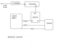
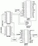
Ok the first diagram has an obsolete part CS8402A with TXP outputing a RS422 compatible line driver. The datasheet makes no mention of the clock coming out of TXP.
I like the second diagram, The 74HC244N looks like what I need. It should be something I could add to the DDAC1543 MKII SPDIF reciever board. That board is identical except he uses a 74VHC4040M to do the same thing as the IC1 and IC2 are doing here. It looks like he has the CS8414 in the same mode.
I like the second diagram, The 74HC244N looks like what I need. It should be something I could add to the DDAC1543 MKII SPDIF reciever board. That board is identical except he uses a 74VHC4040M to do the same thing as the IC1 and IC2 are doing here. It looks like he has the CS8414 in the same mode.
- Status
- This old topic is closed. If you want to reopen this topic, contact a moderator using the "Report Post" button.
- Home
- Source & Line
- Digital Line Level
- Its always better to slave the transport blah blah blah