Hi Max, Sylvain and everybody.
No, I did not assemble John's dac yet. It will come for sure.
It was Thomas's dac (Tube Lover).
Sylvain got confused here may be. We had an excellent night.
Sylvain, I am working on a tube output for this dac. Should be ready in a few days.
Jean-Charles
No, I did not assemble John's dac yet. It will come for sure.
It was Thomas's dac (Tube Lover).
Sylvain got confused here may be. We had an excellent night.
Sylvain, I am working on a tube output for this dac. Should be ready in a few days.
Jean-Charles
Adhoc, very well said. May be some of the more "learned" members who needs to brush up on their manners should take Adhoc's reasonable suggestion to heart. I wouldn't hold it against anyone on this board if he or she had no idea that the olfactory system can perform hierarchical categorization of odors or how the somatorsensory map of the postcentral gyrus is layed out. I certainly don't feel superior because of it, and I would be happy to explain it in private email if someone was interested.

Hi Adhoc;
Well said. ( Good to see more coleagues here") )
)
Then again, lets not focus on this topic ethernally... too noisy.
I'm sure our more knowledgeable mates are great guys and we surelly would have a great time listening to some music and drinking spirituous beverages toghether. Also, they certainly are a fountain of digital wisdom (and I am not being ironical at all). The problems are:
a) style of posts (wich could be more diplomatic (and well intentioned. Ooops!)).
b) given their skills, they could easily test the proposed project and discard good performance. That, in the hypothetical case that they grant the benefit of the doubt...
Humbly yours,
M
PS: so tubelover's DAC was it. Good to know.
PS2: I don't see tubelover's TDA1541A groupbuy anymore...someone knows where is it?
Well said. ( Good to see more coleagues here
)Then again, lets not focus on this topic ethernally... too noisy.
I'm sure our more knowledgeable mates are great guys and we surelly would have a great time listening to some music and drinking spirituous beverages toghether. Also, they certainly are a fountain of digital wisdom (and I am not being ironical at all). The problems are:
a) style of posts (wich could be more diplomatic (and well intentioned. Ooops!)).
b) given their skills, they could easily test the proposed project and discard good performance. That, in the hypothetical case that they grant the benefit of the doubt...
Humbly yours,
M
PS: so tubelover's DAC was it. Good to know.
PS2: I don't see tubelover's TDA1541A groupbuy anymore...someone knows where is it?
hi max,
directly email to me will be Ok.
thomas_siu@hotmail.com
groups buy only for AS2 grade chips.
thx
thomas
directly email to me will be Ok.
thomas_siu@hotmail.com
groups buy only for AS2 grade chips.
thx
thomas
hi john,
U paid too much effort for his DAC.
Big Thumb for U.
hi all,
In my opinions as adhoc,
we all enjoy diy, Do it yourself, pls less noisy I thought we all love this forum, pls use your effort to protect for it..
The last that I like to say was I saw some message claimed that some ebayers was sold their clone parts in ebay which was made In CHINA. Such as Nelson & others design. That's why I suggested john not to send his files to china to produce PCB's. I understood that PCB made by Oversea's factory all Diyer will pay more. But lf U considerate john paid much effort day by day to test, design. I thought we must support for him. Otherwise all items were copy, copy, copy. Nobody will like to share their point of view & design too.
thx
thomas
8 NOS DAC and CD104
Hi
I have 5 Philips CD104's
Three of them I have modificated to NOS (removing SAA 7030
and puting SAA7000 in 14 bit mode by setting pin 16 high)
I realy like this thread started by ECDESIGNS
His DAC uses I2S (dataline = L+R) and pin 27 on the TDA1541A is high (+5v).
The cd104 has no I2S but DLCF and DRCf separate.
To use that with the TDA1541A (I have a bunch of S1's)
pin 27 has to be low (-5v) placing the TDA1541A in simultaneous L and R data mode
I want to use this NOS DAC (no filtering !!!).
Is this possible with separate simultaneous L and R datamode looking at inverting data and or WS to the second or furter odd TDA1541A.
Thanks in advance for looking at this.
Regards
Onno
Rotterdam
The Netherlands
Re: 8 NOS DAC and CD104
How many TDA1541's do you plan to use?
Onnosr said:Hi
I have 5 Philips CD104's
Three of them I have modificated to NOS (removing SAA 7030
and puting SAA7000 in 14 bit mode by setting pin 16 high)
I realy like this thread started by ECDESIGNS
His DAC uses I2S (dataline = L+R) and pin 27 on the TDA1541A is high (+5v).
The cd104 has no I2S but DLCF and DRCf separate.
To use that with the TDA1541A (I have a bunch of S1's)
pin 27 has to be low (-5v) placing the TDA1541A in simultaneous L and R data mode
I want to use this NOS DAC (no filtering !!!).
Is this possible with separate simultaneous L and R datamode looking at inverting data and or WS to the second or furter odd TDA1541A.
Thanks in advance for looking at this.
Regards
Onno
Rotterdam
The Netherlands
How many TDA1541's do you plan to use?
Jean-Charles said:Hi Max, Sylvain and everybody.
No, I did not assemble John's dac yet. It will come for sure.
It was Thomas's dac (Tube Lover).
Sylvain got confused here may be. We had an excellent night.
Sylvain, I am working on a tube output for this dac. Should be ready in a few days.
Jean-Charles
Sorry for my mistake. I tough it was this dac that we where listening.
Sylvain
tube-lover said:
The last that I like to say was I saw some message claimed that some ebayers was sold their clone parts in ebay which was made In CHINA. Such as Nelson & others design. That's why I suggested john not to send his files to china to produce PCB's. I understood that PCB made by Oversea's factory all Diyer will pay more. But lf U considerate john paid much effort day by day to test, design. I thought we must support for him. Otherwise all items were copy, copy, copy. Nobody will like to share their point of view & design too.
thx
thomas
This is an honest point of view, Thomas.
but....
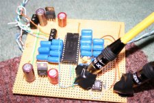
I have to admit I was hoping you'd offer to have the PCBs made at your friends factory ( the vga card manufacturer ). Your boards look stunning !
Goodness me.
After a week away, it all kicks off!
Well, I think this thread is invaluable, like others. I think many benefit from all kinds of levels.
Perhaps, for some, its the debate of sampling theory (I admit I'm uneasy about the maths, but there is no perfect conversion process in practice, as I have learnt from this thread, so am more open minded).
For others, its the building of the actual DI DAC.
Anyway, for me, I've managed to learn about the 1541, tapping off I2S, sensible reclocking, differential RX and TX, DEM reclocking etc.
Because of this, I have built my first (unfiltered, still learning about the pros and cons of that) NOS DAC.
Now, I'm off to fit the differential RX/TX, then think about a clock module (might reuse and mod my Kwak clock from elsewhere) to reclock the I2S, and maybe investigate DEM reclocking to start.
So, John, thanks for starting this thread, because I have learnt loads, and started building DACs.
Cheers,
Phil
Attachments
Re: Cd104
First off, this is a big job, so you might want to consider Bernhard's suggestion in post 247. Now back to the task at hand.
You have a number of choices, none easy.
1.You add could a SPDIF transmitter.
2.You could serialize and reformat the data as I2S, Left or Right justified.
If you go down either of the above routes you can use the DIDAC as is. Note you have have to change the data from offset binary to binary two's complement. Also note in order to do 1. you have to do 2. so...
3.Design a delay chain specifcally for the SAA7000 and the TDA1541A in simultaneous mode.
Onnosr said:Thank you RFBRW to look at my question.
I want to put on 4 tda1541A's or even 8.
But even using only 2 TDA's the question is the same I think.
Onno
First off, this is a big job, so you might want to consider Bernhard's suggestion in post 247. Now back to the task at hand.
You have a number of choices, none easy.
1.You add could a SPDIF transmitter.
2.You could serialize and reformat the data as I2S, Left or Right justified.
If you go down either of the above routes you can use the DIDAC as is. Note you have have to change the data from offset binary to binary two's complement. Also note in order to do 1. you have to do 2. so...
3.Design a delay chain specifcally for the SAA7000 and the TDA1541A in simultaneous mode.

octal D-I DAC design issues
Hi all,
Thanks for all compliments and support,
I will try once more to explain why I built the octal D-I DAC like this.
Like many other people I was not happy with the sound produced from commercial CD players and DAC's. One day I read some articles about NOS DAC's, so I decided to give it a try.
This resulted in designing the twin DAC using a differential setup. The differential setup seemed to reduce noise and canceled the DC component of the DAC chip's used. So a fully DC coupled DAC could be constructed without capacitors in the signal path. And yes, like so many other people that build a NOS DAC, I encountered the problems with the mirror images above fs/2 (intermodulation in the audio range). I decided to design a suitable analog filter that attenuated them to a point, interference was almost inaudible. This resulted in a 8th order butterworth filter (twin dac schematics at the start of this thread). This worked fine and I used it for some time. If people want to try a relatively simple NOS DAC, this would be a nice project to start with. It uses one double sided PCB.
Then I started experimenting with another technique, using multiple DAC's to simulate a digital filter. Linear interpolation was the easiest way to go. By creating 7 interpolated samples, each step was now divided into 8 individual steps, creating samples with 2.83uS intervals instead of the usual 22.6uS intervals. I used 8 separate DAC's so amplitude resolution increased as well (from 16 to 19 bits), this means 524,288 values instead of 65,535. Another advantage from this setup is noise reduction. So a form of digital filtering is used that needs no oversampling. Why is this so important? because oversampled DAC's even with the best digital filters available are very sensitive to jitter. Like the twin DAC, the octal D-I DAC uses a differential DAC setup to enable a fully DC coupled system.
This D-I technique can be extended to 63 interpolated samples using "slow" DAC's, I already tried this (32 DAC setup using the TDA1543). The output signal becomes very smooth, and frequencies above fs/2 are effectively attenuated.
Linear interpolation is easy to implement, maintaining the NOS DAC phase linearity. It mainly causes errors at higher frequencies as it reduces waveform energy, causing an early high-frequency rolloff. This can be seen on some oscillograms I posted earlier. This doesn't seem to be a problem in practice. What we do gain is a open transparent sound without audible high frequency interference and a very natural sound quality. This is mainly caused by lower jitter sensitivity, higher resolution and the absense of a high order analog filter that causes phase linearity errors.
But, for the perfectionists, the linear interpolated samples can be replaced by calculated samples using the appropriate reconstruction algorytm. A DSP can replace the timing chain module and send the correct interpolated samples to each individual DAC. The advantage of such a system is it's low jitter sensitivity and the possibility to create 63 interpolated samples with relatively slow logic, it can be viewed as a high performance real-time parallell processing system. Because BCK is still used for timing, DSP output jitter on both DATA and WS signals are no problem. Question remains, will it sound better than the current octal D-I DAC setup. But it might be a possible future upgrade.
I/V conversion, after some experiments I decided to use a op-amp based I/V converter. First it ensures a very low voltage on the TDA1541A current output, this is absolutely necessary to keep distortion low. Using passive conversion would inevetably cause too high voltages on the current output (distortion) and noise / hum problems due to the high amplification needed. Using transformers would add another non-linear component in the signal path and make DC coupling impossible. The op-amp I/V converter was tuned to obtain best possible feedback characteristics, this is documented on this thread as well. If the feedback mechanism works optimal, the grainy sound is completely gone.
Then about the tubes, first I used high-quality operational amplifiers only (OPA627), it's known that semiconductors mainly generate odd harmonic distortion. Odd harmonic distortion sounds unpleasant and even the slightest distortion of this type degrades sound quality. Even the OPA627 needs to "warm up" to achieve lowest distortion, and yes this effect is clearly audible, if the OPA627 isn't warmed up, it doesn't sound that good. Then I decided to try a tube output amplifier on the octal D-I DAC, it sounded more open, natural and transparant. I liked this soo much, a tube output amplifier was added to the octal D-I DAC. Then I accidently connected both the opamp and the tube output together during swapping between tube and op-amp. This sounded better than anything I had heared so far. After many experiments, I found a ratio between op-amp and tube output that sounded very natural. A explanation for this could be that the odd harmonic distortion from the OPA627 is compensated by adding the correct amount of even harmonic distortion from the tube output. The octal D-I DAC will be able to switch between op-amp, tube and mixed mode. A output attenuator maintains correct output amplitude.
Next the interface used, at first I used a differential SPDIF interface, and like many others spend a lot of time optimizing the jitter performance. But once I heared the sound using direct I2S, I decided to no longer use SPDIF, but use differential I2S exclusively. This however imposed a problem, there are two different formats, the philips and the sony format. So in order to provide a flexible I2S interface, the dual format timing chain was developed.
Recently the USB to I2S module was developed using a unique shift register reclocker that produced sound quality equal to direct I2S. So the octal D-I DAC will now get both, I2S inputs and a USB input. Maximum USB cable length (5m) can be used without sound quality degradation.
Interfacing, when a digital sound source has got I2S outputs, these can either be connected directly to the analog mainboard, or by adding differential drivers like the DS8921 and DS8922 when a longer interlink is used. Yes after all tests, these still seem to work best and are quite immune to interference. Very important is to use a separate driver chip for BCK exclusively. For example, a single DS8921 for BCK and a double DS8922 for both WS and DATA, so never combine BCK with other I2S signals using the same chip!
If a digital sound source hasn't got I2S outputs, they could be derived directly from the chip, like I did with the sony CD changer. If there is no way to obtain I2S outputs, the SPDIF output can be used in a special way. Add a audio interface chip (CS8412, CS8414 or DIR1703) and synchronously reclock the chip's I2S outputs with the master clock (use 2 cascaded flipflops for each signal). Make sure a separate chip is used for reclocking BCK exclusively. If there is no (usable) master clock present, the shift register reclocker can be used for BCK.
The output signal becomes very smooth, and frequencies above fs/2 are effectively attenuated.
This is simply untrue... What compounds this is the fact that your recovery filter has a corner frequency of 80 kHz. So, all the image frequencies below that are alive and well. Look for them, and you will find them.
This is the exact point which is continually ignored here.
hi jean-paul,
very thanks for your comment for my stunning PCB. They all produce in my uncle's display card factory in taiwan. This can gurantee that will not to expose the detail john's file to public. Only in forum. After they funish My uncle will send to me or can directly call him post to overseas.
But I asked for him already, he hadn't Telfon PCB base material.
Computor wil not use telfon PCB, only very HF communication & Military equ will use. I will do my best to assiatance for john, if he need.
Hi john, if the price was too expensive for your factory to produce PCB. I can help U, PCB send to Taiwan made, not need to worry as china will copy.
Hope I can help.
so it means Standard TDA1541a chips & PCB I can help U if U not need telfon PCB.
thx
thomas
Hi EC, thanks for the recap of your design choices, very informative.
But I do have several questions:
1) "But, for the perfectionists, the linear interpolated samples can be replaced by calculated samples using the appropriate reconstruction algorytm. A DSP can replace the timing chain module and send the correct interpolated samples to each individual DAC."
Is there a DSP out there that has been preprogrammed with appropriate reconstruction algorythms or does one need to program the DSP from scratch? It would be very interesting to compare the sound of linear interpolation with DSP reconstructed data.
2) "Using transformers would add another non-linear component in the signal path and make DC coupling impossible."
Some would consider the transformer output would be the purest approach. I thought DC coupling would be possible if you used the balanced taps on the transformer? Sorry for my ignorance.
3) "Then I decided to try a tube output amplifier on the octal D-I DAC, it sounded more open, natural and transparant."
In the strictest sense, isn't the tube output on your DAC a tube output buffer, not a tube amplifier? I thought the I/V conversion must also be handled by a tube rather than an Opamp to be considered a tube output amplifier. Do you think this would be too noisy?
4) "But once I heared the sound using direct I2S, I decided to no longer use SPDIF, but use differential I2S exclusively."
Could you still offer the plain old SPDIF connection for some of us who may not be able to get I2S or USB connection right away?
Thanks.
Re: octal D-I DAC design issues
Let me just say before the usual suspects issue a fatwa that I am not in anyway questioning the sound of the DIDAC just the explanation of the technology behind it.
ecdesigns, you can't have it both ways. You can trade amplitude resolution for time resolution or vice versa but you can't have an increase in both without a physical increase in both. The TDA1541A is a 16bit dac and even if you stagger an infinite amount of them the quantization steps will remain the same. Yes, you have more samples but they are still only 16 bit representations. There is simply no way you have 500,000+ values. What the octal DIDAC has is 352,800 16 bit samples per second with each sample retaining its 16 bit quantization. What you have is a dac equivalent to 19 bits at 44K1. Each doubling of the sample rate is the equivalent of adding a bit and remaining at original sample rate. This is the basis of the one bit dac. Wordlength is traded for a massive increase in sample rate.
-ecdesigns- said:
Then I started experimenting with another technique, using multiple DAC's to simulate a digital filter. Linear interpolation was the easiest way to go. By creating 7 interpolated samples, each step was now divided into 8 individual steps, creating samples with 2.83uS intervals instead of the usual 22.6uS intervals. I used 8 separate DAC's so amplitude resolution increased as well (from 16 to 19 bits), this means 524,288 values instead of 65,535. Another advantage from this setup is noise reduction. So a form of digital filtering is used that needs no oversampling. Why is this so important? because oversampled DAC's even with the best digital filters available are very sensitive to jitter. Like the twin DAC, the octal D-I DAC uses a differential DAC setup to enable a fully DC coupled system.
Let me just say before the usual suspects issue a fatwa that I am not in anyway questioning the sound of the DIDAC just the explanation of the technology behind it.
ecdesigns, you can't have it both ways. You can trade amplitude resolution for time resolution or vice versa but you can't have an increase in both without a physical increase in both. The TDA1541A is a 16bit dac and even if you stagger an infinite amount of them the quantization steps will remain the same. Yes, you have more samples but they are still only 16 bit representations. There is simply no way you have 500,000+ values. What the octal DIDAC has is 352,800 16 bit samples per second with each sample retaining its 16 bit quantization. What you have is a dac equivalent to 19 bits at 44K1. Each doubling of the sample rate is the equivalent of adding a bit and remaining at original sample rate. This is the basis of the one bit dac. Wordlength is traded for a massive increase in sample rate.
Re: octal D-I DAC design issues
Hi Ec,
you hear high frequency rolloff as you hear high frequency boost as you hear low level distortion.
CDs may sound more relaxed and less aggressive with a high frequency rolloff.
A frequency rolloff like in your DAC ( how much is it at 15 kHz ? ) makes a big big difference.
I think it is a win and loose game:
OS may be more jitter sensitive and may have wrong samples from interpolation, calculation, rounding.
Non os has problems with phase errors from firewall analog filters or if you not use them, with mirror images and frequency response errors.
Linear interpolation still got problems with mirror images and frequency response errors while additionally introducing distortion caused by wrong samples at higher frequencies.
In the end what sounds best may be a matter of taste.
-ecdesigns- said:
Linear interpolation is easy to implement, maintaining the NOS DAC phase linearity. It mainly causes errors at higher frequencies as it reduces waveform energy, causing an early high-frequency rolloff. This can be seen on some oscillograms I posted earlier. This doesn't seem to be a problem in practice. What we do gain is a open transparent sound without audible high frequency interference and a very natural sound quality.
Hi Ec,
you hear high frequency rolloff as you hear high frequency boost as you hear low level distortion.
CDs may sound more relaxed and less aggressive with a high frequency rolloff.
A frequency rolloff like in your DAC ( how much is it at 15 kHz ? ) makes a big big difference.
I think it is a win and loose game:
OS may be more jitter sensitive and may have wrong samples from interpolation, calculation, rounding.
Non os has problems with phase errors from firewall analog filters or if you not use them, with mirror images and frequency response errors.
Linear interpolation still got problems with mirror images and frequency response errors while additionally introducing distortion caused by wrong samples at higher frequencies.
In the end what sounds best may be a matter of taste.
- Home
- Source & Line
- Digital Line Level
- Building the ultimate NOS DAC using TDA1541A