Unfortunately no Max. Always stayed away from high voltage diy stuff for fear of being electrocuted. Lol Hence my tube amps are commercial stuff. Having said that I have forgo this fear & am collecting stuff to build a PSE 300B amp. At the same time also researching & learning on schematics.
Cheers
Cheers
Dear Brothers and Sisters, here I come, in front of all the congregation, to confess my Sin.
I started modifying the MOSAIC.
The MOSAIC DAC is a truly great DAC, exquisitely detailed, relaxed and elegant, but, in stock form, it lacks hard punch in the mid-bass and bass weight, so it always looses compared with my Otari R2R. Talking about which, I thank that one, which is heavily modified, and whose last couple of mods not only catapulted it to high class status but also encouraged me to attempt the challenge for the MOSAIC.
I'll explain. From a past audiophile life I have still some Black-Gate caps (I don't care what your opinion is
I have used baluns since the beginning of my DIY life, mainly in SMPS driven units, using highQ cores (stated effect until multi KHz range) and OCC copper enameled wire, which is the best option, but I have also used those rings that come in PC SMPS and common type enameled wire and it still is good. Now I have instaled baluns in linear PS units, and now I have the will to install them also in power amps just to see what it does. Maybe I will install them on all home appliances.
Anyway, it is a very cheap and easy to do mod, so there you have...
Back to the MOSAIC: I have always suspected the power supply as the cause for the "sound presentation" and after the expiration of the waranty period (or not?
Because the complexity and secrecy of the circuit, no one in his right mind
The principal daughter board has several caps (excellent quality, BTW) that are easy to swap for my preferred ones. I replaced three 330uF caps for 560uF Rubycon ZLH (I lacked ZL) which were the only ones that I had that fitted there.
I now you will doubt it but the effect was, as predicted, much more punch on the mid-bass and more extension to the lower bass. A bit of delicacy was lost, though...detail remained and with a bit of more dynamics, IMHO.
Then the Balun: my last high Q core, but with common type copper; great effect; more depth and credibility of images; more "curves" and breath to the sound.
Now I am testing the latest mod: B-G PK series on the converter's PS. There is some space constraints so I could not test "power bank" or "super-E cap" there, but I found a place where I will be able to test this approach with N series B-G caps in the near future...well the BGs are doing well: refinement returned, details are still even or greater and frequency extremes are wider apart. It is still sounding a bit "plastic" though. I hope that goes away soon.
That's all for now. I hope our Guru will forgive my sacrilege.
Fully completed products are a torture for us, DIYers.
Best wishes,
M.
Interesting stuff. Have you measured the voltage and current draw from the main PS board? Maybe it's possible to make an external PSU. A big transformer and a choke or two would probably be a nice thing to try out. Those board connectors would make it non destructive (unless of course you fry something with overvoltage).
Regards, V
Last edited:
Interesting stuff. Have you measured the voltage and current draw from the main PS board? Maybe it's possible to make an external PSU. A big transformer and a choke or two would probably be a nice thing to try out. Those board connectors would make it non destructive (unless of course you fry something with overvoltage).
Regards, V
Thanks guys,
It certainly is a small current draw. An external power supply (at least TX part) could well be built, with "Reisert Baluns" pre-post it, and a bigger capacitance can be added inside the original box. At the moment I don't feel quite like doing this.
Dear Xaled wrote:
Here comes another one - what is the basis for the number of turns?
Whatever the Good Lord tells me is good enough.
Try one layer first with all the turns that fit well.
I have tried three layers on units that I feel are noisier. That increase capacitance, apart inductance. I wish I had the instruments to do a little research about all this: effects of different materials and n° of turns on noise.
Dear Sumotan wrote:
am collecting stuff to build a PSE 300B amp. At the same time also researching & learning on schematics.
Same here. Never tried tubes for risks. I suspect some of the magic comes from tube rectification. We talked previously about Thyratron's rectification.
That one is interesting! 
Have you tried VFETs? I love them. Triode response with power FET precision. Sounds like heaven. My last amp has VFETs bootstrapping a Darlington output.
Sorry for OT. Ego sometimes still wants to opine.
Best wishes of success for all my fellow DIYers.
M.
(Copied from my Amnesis thread)
I've been asked how many turns for the "Reisert Bifilar Balun"?
Based on recent listening, I believe the more the better. I will probably re-wind some and see/listen.
I appears that R and C vary with N (n° of turns) but L vary with N squared, which apparently brings the resonant point lower...I hope this is a good thing
Anyway, there you have, probably the best and cheapest upgrade of them ALL.
Best wishes,
M.
Attachments
Hi Max
Thanks for sharing. My own experience is when you have to many turns sound will slow down a little & you loose dynamics. I believe core material is very important too as I've experience sound to be darker. Perhaps your way of winding will not have such adverse effect as I've experience. Will give it a try.
Thanks again
Thanks, Sumotan, for the confidence.
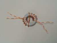
Just remember to follow the diagram: bifilar winding with halfway inversion of sense of rotation. You are free to try one, two or three layers.
As you state, better materials give better results but are more expensive. I have access to many broken SMPS where I can extract the ferrite rings and some streets away there is a commerce where I can buy enameled wire by the kilo. I bought some for my "free energy" projects. So, it is a very cheap trick indeed.
Good luck,
M.
Just remember to follow the diagram: bifilar winding with halfway inversion of sense of rotation. You are free to try one, two or three layers.
As you state, better materials give better results but are more expensive. I have access to many broken SMPS where I can extract the ferrite rings and some streets away there is a commerce where I can buy enameled wire by the kilo. I bought some for my "free energy" projects.
So, it is a very cheap trick indeed. Good luck,
M.
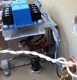
I started a thread on the Power Supply section and some are jumping in with all kinds of safety concerns, justified, BTW.
Please use good quality "thick enamel" wire (or better) and painted/coated ferrite rings. Check for proper insulation with tester prior to connect. Start with low power circuit.
Thanks and enjoy.
M.
Please use good quality "thick enamel" wire (or better) and painted/coated ferrite rings. Check for proper insulation with tester prior to connect. Start with low power circuit.
Thanks and enjoy.
M.
Hi Max,
I don't get it what's this thing about safety, add a fuse. Aren't trafo wound this way with enamal wires & yet ???? Anyway I tried it already using only 1 layer & it works Max but you don't get something for nothing. You hear deeper in the recordings, sound like Cymbal crash becomes more realistic. Cons images becomes larger & forward sounding. Now you've open up a can of worms for me. Ferrite ring size & enamal wire gauge used will surely have an effect as well not mention how many layers.
Thank again Max for sharing
Hi Max,
My suspicion has proven correct. Wire gauge matters.
I started with 0.8 mm enamel wire wound around a 40 mm powder coat Ferrite ring.
Sound reported as above. Change wire gauge to 1mm & all the cons are gone. This Balun is connected to my dac & sd card player which has it's own trafo. Sound now is expansive with nice details & non fatigue. Perhaps installing on all equipment might not be good as it cleans up the system too much causing it to sound too clinical. Why do I say this cause my tube amp don't sound so tubey now. Lol
Hi maxlorenz,
We have to face the fact that the mains is polluted like never before and pollution will continue to increase. Unlike say 50 years ago there is now dominating RF noise on the mains that mixes with WIFI, Bluetooth, radar, and GSM. Home solar power (SMPS inverters) will produce highest interference by far, if you or your neighbours have such SMPS inverter installed, forget about high performance mains powered audio.
My personal experience with (common mode) mains filters is that the sound gets "slower", softer, and transient impulse response suffers. The filter basically adds extra -impedance- in series with the transformer primary, this will limit peak charge currents for charging the smoothing caps. This will probably have highest impact on power amps.
The most effective way of cleaning up the mains is using balanced power. This is basically an isolation transformer with 230V primary and 2 x 115V secondary (or 120V primary and 2 x 60V secondary). The secondary windings are placed in series and the centre tag is connected to safety earth. This way interference is cancelled like with balanced interfaces.
RF filters (low inductance) usually work fine and could be added to balanced power. Don't forget to use iron powder ring cores for suppression of very high frequencies.
The common mode filters you constructed may cause short circuit (thin insulation) in the event of a power surge or when the insulation gets damaged by 50Hz vibration. It is best to use double lacquered copper wire (stronger insulation, high melting point of the insulation). Also dip the complete assembly in suitable lacquer so the wiring can't resonate and rub-off insulation over time.
Usually common mode filters have two separate (isolated) windings in order to prevent short circuits.
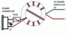
The way you have drawn the balun, both windings do not cancel but add. So the net result is a plain common-mode filter. This winding technique is often used in RF (insulation) transformers in order to improve signal coupling at high frequencies.
It would be even better to use wire with thicker heat resistant insulation (PTFE) that is rated for applied mains voltage. When using lacquered copper wire I strongly suggest to add a fuse between both, mains inlet and the common mode filter. There is a PCB fuse soldered on the power supply PCB of the Mosaic UV, but it won't be of any use when the common mode filter placed in front of it shorts out.
Since you are already modding the Mosaic UV, it is quite easy to power the Mosaic UV DAC using two 12V batteries for required +12V and -12V supply. As mains noise levels keep rising, battery power supply and efficient (low power) audio components may be the best option.
Digital audio comes with a number of fundamental flaws that haven't been identified nor fixed yet. That's why one can spend decades on tweaking without getting consistent results. As one continues to tweak, the external factors (mains noise, digital audio source noise, EMI) keep changing too. Because digital audio is -extremely- sensitive to this kind of noise, it's like attempting to dry a room while the water is pouring in.
Another thought, suppose you tweak / optimise a DAC at home with local mains interference spectrum, digital audio source noise, ground loop noise spectrum and connected audio equipment.
When you take that DAC to another place and connect it there, it may sound completely different as all external factors have changed.
We have to face the fact that the mains is polluted like never before and pollution will continue to increase. Unlike say 50 years ago there is now dominating RF noise on the mains that mixes with WIFI, Bluetooth, radar, and GSM. Home solar power (SMPS inverters) will produce highest interference by far, if you or your neighbours have such SMPS inverter installed, forget about high performance mains powered audio.
My personal experience with (common mode) mains filters is that the sound gets "slower", softer, and transient impulse response suffers. The filter basically adds extra -impedance- in series with the transformer primary, this will limit peak charge currents for charging the smoothing caps. This will probably have highest impact on power amps.
The most effective way of cleaning up the mains is using balanced power. This is basically an isolation transformer with 230V primary and 2 x 115V secondary (or 120V primary and 2 x 60V secondary). The secondary windings are placed in series and the centre tag is connected to safety earth. This way interference is cancelled like with balanced interfaces.
RF filters (low inductance) usually work fine and could be added to balanced power. Don't forget to use iron powder ring cores for suppression of very high frequencies.
The common mode filters you constructed may cause short circuit (thin insulation) in the event of a power surge or when the insulation gets damaged by 50Hz vibration. It is best to use double lacquered copper wire (stronger insulation, high melting point of the insulation). Also dip the complete assembly in suitable lacquer so the wiring can't resonate and rub-off insulation over time.
Usually common mode filters have two separate (isolated) windings in order to prevent short circuits.
The way you have drawn the balun, both windings do not cancel but add. So the net result is a plain common-mode filter. This winding technique is often used in RF (insulation) transformers in order to improve signal coupling at high frequencies.
It would be even better to use wire with thicker heat resistant insulation (PTFE) that is rated for applied mains voltage. When using lacquered copper wire I strongly suggest to add a fuse between both, mains inlet and the common mode filter. There is a PCB fuse soldered on the power supply PCB of the Mosaic UV, but it won't be of any use when the common mode filter placed in front of it shorts out.
Since you are already modding the Mosaic UV, it is quite easy to power the Mosaic UV DAC using two 12V batteries for required +12V and -12V supply. As mains noise levels keep rising, battery power supply and efficient (low power) audio components may be the best option.
Digital audio comes with a number of fundamental flaws that haven't been identified nor fixed yet. That's why one can spend decades on tweaking without getting consistent results. As one continues to tweak, the external factors (mains noise, digital audio source noise, EMI) keep changing too. Because digital audio is -extremely- sensitive to this kind of noise, it's like attempting to dry a room while the water is pouring in.
Another thought, suppose you tweak / optimise a DAC at home with local mains interference spectrum, digital audio source noise, ground loop noise spectrum and connected audio equipment.
When you take that DAC to another place and connect it there, it may sound completely different as all external factors have changed.
Hi guys. 
Thanks for the inputs.
Dear Sumotan, do both halves before the second winding, for increased, physical integrity. Yes, apparently lower gauge n° is better and usually has thicker insulation. I do not feel slower sound. I hear deep into the recordings, with sweetness and color and textured melodic lines, with rich detail and harmonics, for example in massed strings, etc. Dynamics are great, with my beloved Amnesis amp. I should try this with my First One amp that uses a Hypex SMPS.
Dear -EC-, indeed, I use balanced power for more than a decade in both of my main systems.
This a special choke. I do not fully (nor minimally) understand how it works but perhaps it has to do with exactly matching currents and dissipating energy. Note the inverted sense of rotation of the halfway winding technique.
Of course PTFE or other insulators can be used, but usually at higher cost. No problem with bigger chokes that can handle it.
I used to immerse the balun into varnish, which is slow to dry. Now I use hot glue to fix and avoid some risk. In case of getting hot, the smell of the glue will warn me of troubles.
I have though about a short. Like it is now, the main house brake will be triggered instantly.
Anyway, I have used this trick for around 15 years without any troubles.
Cheers,
M.
Edit: why double posting???
Thanks for the inputs.
Dear Sumotan, do both halves before the second winding, for increased, physical integrity. Yes, apparently lower gauge n° is better and usually has thicker insulation. I do not feel slower sound. I hear deep into the recordings, with sweetness and color and textured melodic lines, with rich detail and harmonics, for example in massed strings, etc. Dynamics are great, with my beloved Amnesis amp. I should try this with my First One amp that uses a Hypex SMPS.
Dear -EC-, indeed, I use balanced power for more than a decade in both of my main systems.
This a special choke. I do not fully (nor minimally
) understand how it works but perhaps it has to do with exactly matching currents and dissipating energy. Note the inverted sense of rotation of the halfway winding technique.Of course PTFE or other insulators can be used, but usually at higher cost. No problem with bigger chokes that can handle it.
I used to immerse the balun into varnish, which is slow to dry. Now I use hot glue to fix and avoid some risk. In case of getting hot, the smell of the glue will warn me of troubles.
I have though about a short. Like it is now, the main house brake will be triggered instantly.
Anyway, I have used this trick for around 15 years without any troubles.
Cheers,
M.
Edit: why double posting???
Last edited:
Hi Max,
Thanks again. Will try double layer another time cause it's sounding great now besides 1mm wire is difficult to work with especially in trying to get tight windings.
Btw it occured to me what if we wind first layer as per you diagram & wind the next layer from the opposite end, would ther be more effective ??? Will go buy more ferrite rings to experiment further.
What you discribe Max is what I hear too but with lower gauge wires there's cons involved hence my recommendation is 1mm diameter wire.
Cheers
Hi maxlorenz,
The crossover at the middle of the winding minimises capacitive coupling between both, input and output by maximising the distance between input and output.
Without it, the output would be located closer to the input and would therefore increase unwanted coupling between both input and output.
The lower the capacitive coupling between both input and output, the better the noise suppression.
So basically it's just a common mode filter choke, nothing magical about it.
This is a common mode filter with two separate windings:
https://images-na.ssl-images-amazon.com/images/I/41iJTIz6+hL._SX342_.jpg
Running both wires in parallel instead of using two separate windings improves coupling between both windings and thus increases the bandwidth for noise canceling.
Coupling can be made even more effective (larger bandwidth canceling) by using twisted pairs (attached photograph).
So this Current Balun simply cancels unwanted RF frequencies in a specific frequency range, typically between 1 - 54 MHz with a good Balun construction.
You could also experiment with current Baluns in the audio signal path (RCA). This could cancel RF ground loop noise that travels along the RCA audio interlinks.
Attachments
Thanks -EC-.
I will try your advises.
I know it operates in VHF/UHF but the effect is noticed even in sub-bass here. Suddenly, everything has depth, layers, curves and low level detail that was previously submerged and hidden.
Great Sumotan.
The guardians closed my thread.
All my units, safe one, have fuses incorporated in the mod.
This mod also works in the secondary of the TX. I will try today both positions, pre and post-TX.
Edit: updated diagram, to comply.
Cheers,
M.
Attachments
Last edited:
Measurements of Hifidiy forum Anniversary TDA-1541 My DIY Replica | Audio Science Review (ASR) Forum
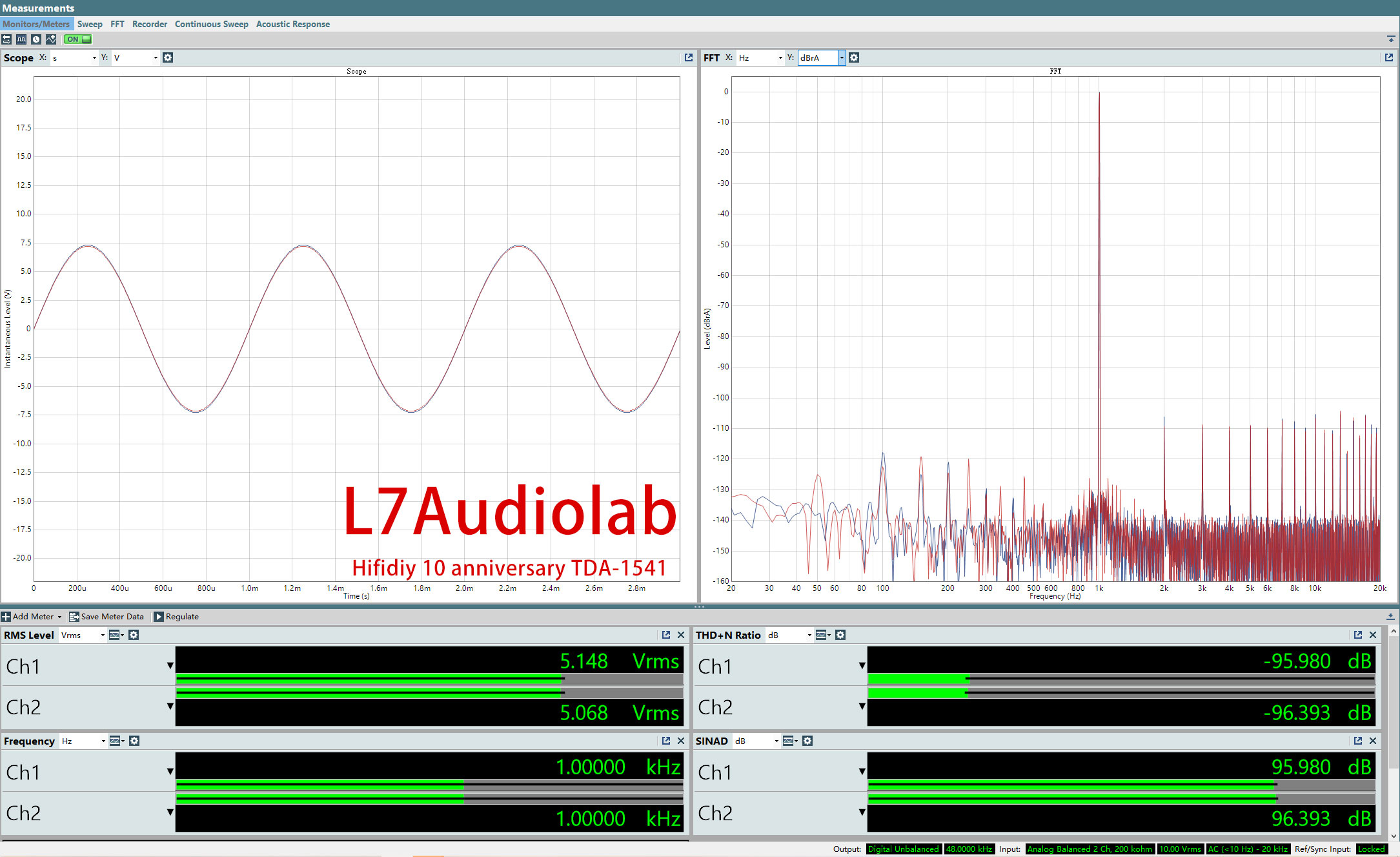
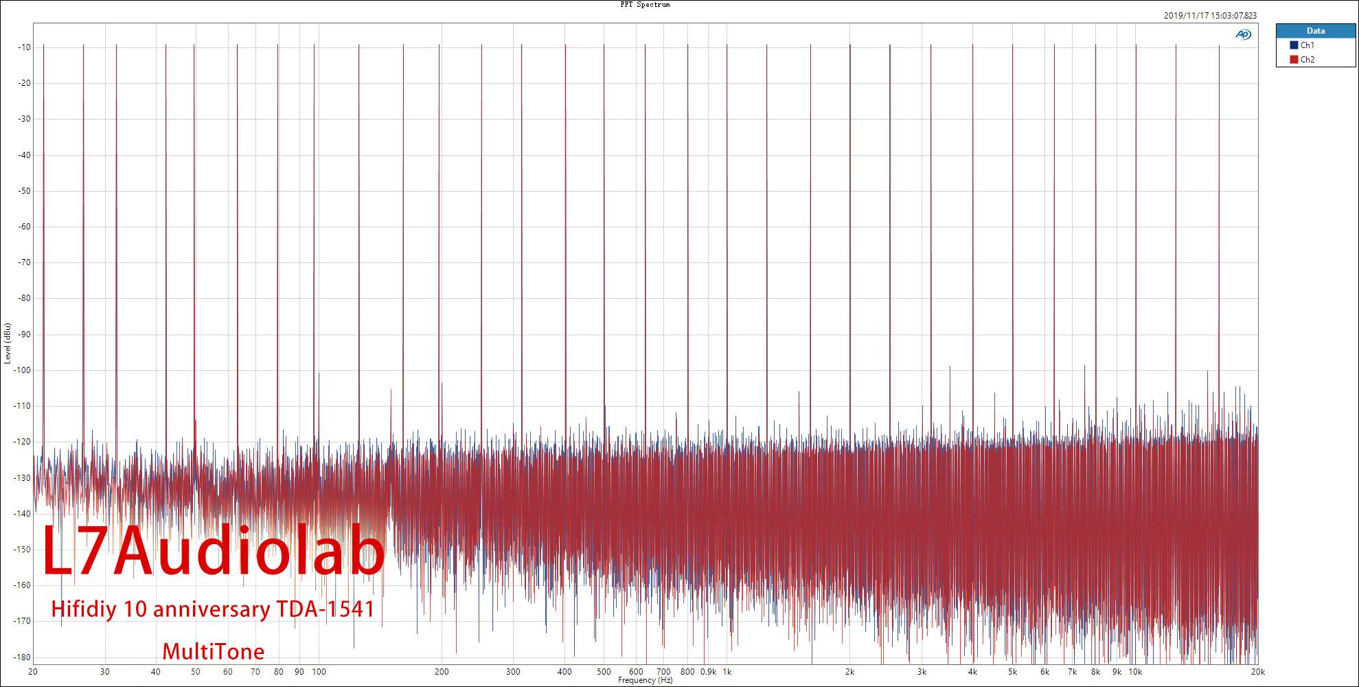
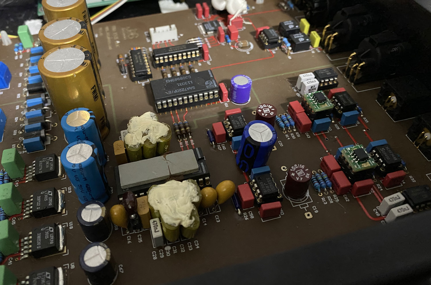
In 2014, the hifidiy.net forum released a series of DIY projects to mark the tenth anniversary of the forum.
This 1541 PCB is based on the 1541 DAC project.
Basically the TDA1315H input, SAA7220+TDA1541 architecture supports RCA and XLR outputs.
Some of the above PCB replicas were made last year. And I made this DAC based on this PCB.
In production, I use JRC5534DD for I/V & OPA1611 for LPF.
Hi John,
Can you provide a sketch showing how these devices are combined/connected.
What is the input interface of the D/A96TF? Can a Toslink source be directly connected or only via the New digital audio interface.
How is the new UPL24E connected to the D/A96TF.
Can I switch between 2 or more inputs via RMC.
We are working on a number of new projects:
1) New digital audio interface
2) USB translator
3) Toslink / Coax translator
4) New UPL24E with PC-based graphic user interface
5) New D/A converter, the D/A96TF
Can you provide a sketch showing how these devices are combined/connected.
What is the input interface of the D/A96TF? Can a Toslink source be directly connected or only via the New digital audio interface.
How is the new UPL24E connected to the D/A96TF.
Can I switch between 2 or more inputs via RMC.
- Home
- Source & Line
- Digital Line Level
- Building the ultimate NOS DAC using TDA1541A