I am still quite puzzled by the way this circuit works. To make it easier to adjust the bias resistors . I first tried to adjust each dac, with the data in disconnected, to 0 V dc, with no connection to the other dac, but that was way off.
If I now measure the DC at the outputs, after the adjustments, and with the two 1 KOhms between the two dac's, the positive dac is @ - 157 mV and the negative is @ +161 mV.
I would , initially , have thought, that both should be @ 0 VDC....
What does the simulation say about this?
If I now measure the DC at the outputs, after the adjustments, and with the two 1 KOhms between the two dac's, the positive dac is @ - 157 mV and the negative is @ +161 mV.
I would , initially , have thought, that both should be @ 0 VDC....
What does the simulation say about this?
I am going to the hospital for some hand-surgery today, so nothin much happens here.
But.
I was thinking , that my next step would be to see if the same results can be achieved, whit using two dacs from the sam TDA1541A. This would be easier to implement.
Next speculation was , what will happen, if I still use two 150 Ohm but connect the with a 10 Ohm trimmer and take the signal out on the wiper and inject the bias at this point also. When I just used 75 Ohms and shorted the two outputs, the od-order harmonics were all gone, so perhaps this will work?
Hi Koldby,
Wish you an easy surgery and a fast recovery!
Easy. Just repeat:
"I am the light. I am the divine vital energy that cures all wounds and heals all injuries."
But I am sure you will be thinking about the circuit during operation!

Best wishes.
M.
Fantastic that you've got it working, very impressive.Hi Hans.
What a coincidence. I have just finished some trimming and measurements, and sat down to post it, when I saw your post
I am not sure I see what you want to do with two in parallel. Could you elaborate that a little or perhaps a schematic?
What I have done is this.
I put trimmers in both bias and I/V resistor in all 4 dac's (2 tda1541A) .
I initially adjusted all the I/V to excatly 150 Ohms and all the bias resistors to 2mA (3,15 K @ 6,3V).
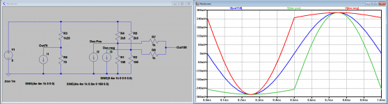
The result was not very good. A lot of even and uneven harmonics. Then I adjusted the bias resistors (long time, they interact) and by this I could trim the uneven harmonics to -100dB. Then I trimmed the I/V. This reduces the even harmonics. Again interacting , not with the other dac but with the bias setting, and that makes perfect sense. I only had a 100 ohm trimmer (in series with a 100 Ohm resistor) and this is way to coarse. But I managed to get to the result in the picture. Pretty impressive right?
This is a -6 dB signal. It clips at 0dB.
With 0dB, the signals on both Dac outputs should look like in the image below.
There you can very well see how precise the tuning has to be done.
Hans
Attachments
In my Sim with no signal applied, one side is 250mv and the other side -250mV.I am still quite puzzled by the way this circuit works. To make it easier to adjust the bias resistors . I first tried to adjust each dac, with the data in disconnected, to 0 V dc, with no connection to the other dac, but that was way off.
If I now measure the DC at the outputs, after the adjustments, and with the two 1 KOhms between the two dac's, the positive dac is @ - 157 mV and the negative is @ +161 mV.
I would , initially , have thought, that both should be @ 0 VDC....
What does the simulation say about this?
So I guess your resistors have a lower value.
Hans
I would be surprised, because this problem has a complete different cause, but nevertheless, trying cost no money.I am going to the hospital for some hand-surgery today, so nothin much happens here.
But.
I was thinking , that my next step would be to see if the same results can be achieved, whit using two dacs from the sam TDA1541A. This would be easier to implement.
Next speculation was , what will happen, if I still use two 150 Ohm but connect the with a 10 Ohm trimmer and take the signal out on the wiper and inject the bias at this point also. When I just used 75 Ohms and shorted the two outputs, the od-order harmonics were all gone, so perhaps this will work?
Succes with your hand surgery.
Hans
Koldby,Hi Hans.
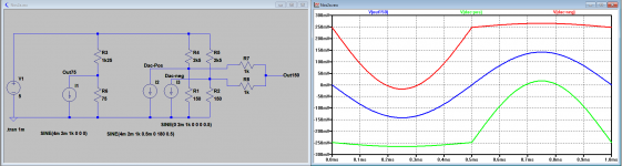
This is a -6 dB signal. It clips at 0dB.
since you tested at -6dB, this is how the signals from both Dac's and at the summed output should look at -6dB and just for completeness.
Hans
Attachments
Just changed the circuit so I now use two dac's from the same TDA1541A and I can adjust it to the same excellent performance. Apparently it is not the time difference, but the level difference that result in elevated even order harmonics. This is good news, as it makes it easier to make a good PCB and I think the circuit will maintain the good performance without readjusting all the time because of temperature drift.
And now even better news!!!


I tried what I suggested earlier:
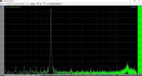
100 Ohm I/V resistor from each dac to ground. A 20 Ohm multiturn trimmer between the two dac output where the wiper is connected to a bias trimmer pot to +6,3V. And the output from the same wiper.
The pic shows a spectrum from a 98% FS signal after trimming bias and the 20 Ohm trimmer. If I raise the input to 99 or 100 % some strange sidebands comes up. Only about -80 dB but it dosent look as clean as this pic. These sidebands are not related harmonic to the main signal
Bye the way THANKS for all the good wishes
I tried what I suggested earlier:
100 Ohm I/V resistor from each dac to ground. A 20 Ohm multiturn trimmer between the two dac output where the wiper is connected to a bias trimmer pot to +6,3V. And the output from the same wiper.
The pic shows a spectrum from a 98% FS signal after trimming bias and the 20 Ohm trimmer. If I raise the input to 99 or 100 % some strange sidebands comes up. Only about -80 dB but it dosent look as clean as this pic. These sidebands are not related harmonic to the main signal
Bye the way THANKS for all the good wishes
Attachments
Just changed the circuit so I now use two dac's from the same TDA1541A and I can adjust it to the same excellent performance. Apparently it is not the time difference, but the level difference that result in elevated even order harmonics. This is good news, as it makes it easier to make a good PCB and I think the circuit will maintain the good performance without readjusting all the time because of temperature drift.
I’m completely surprised, because in my sim there was no level difference between both sides. I only tried a few changes in gain, but with no effect.
But you have proven that the distortion effect of the time shift can be cancelled by trimming the gain.
Good for you, that makes life a bit easier having all dac’s in one encapsulation.
Hans
I have a pair of Sowter 1465 transformers comming from UK shortly, and now I am wondering if I can use them in this circuit. They have two secondary windings (and two secondary) so I can use them to sink the current from the two dac's without magnetizing the core by connecting them in such a way, that the 2mA is in opposite direction in the two primary windings. I would then use two 100 Ohms I/V resistors (trimmable) and a high impedance on the secondary side. Would this work?
Hi koldby,
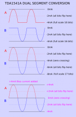
This means changing the polarity of one of the segments by changing the polarity on one of the primary windings.
Remember that the segmented TDA1541A decoder relies on correct polarity of each segment (attached sketch).
By changing the polarity of one of the segments (swapping the connections of one of the primary windings) we would get a signal similar to a full wave rectified signal on the transformer output.
This can be fixed by modifying the decoder circuit so it outputs two in phase signals that are routed to each segment output depending on MSB polarity.
However, you would still have -200mV DC on each 100R I/V resistor that would limit usable output signal swing (TDA1541A output compliance).
So the two +2mA bias sources are still required.
Fine trimming works best by using a suitable shunt resistor and a I/V resistor with a slightly higher value. Use highly stable resistors to minimise temperature related drift.
You could use 120R 0.1% thin film I/V resistors and put a 1K cermet multi-turn trimmer with 330R 0.1% thin film series resistor, in parallel with the 120R 0.1% thin film I/V resistor.
This will give you a fine trimming range between appox. 88 OHms and 110 OHms.
I have a pair of Sowter 1465 transformers comming from UK shortly, and now I am wondering if I can use them in this circuit. They have two secondary windings (and two secondary) so I can use them to sink the current from the two dac's without magnetizing the core by connecting them in such a way, that the 2mA is in opposite direction in the two primary windings. I would then use two 100 Ohms I/V resistors (trimmable) and a high impedance on the secondary side. Would this work?
This means changing the polarity of one of the segments by changing the polarity on one of the primary windings.
Remember that the segmented TDA1541A decoder relies on correct polarity of each segment (attached sketch).
By changing the polarity of one of the segments (swapping the connections of one of the primary windings) we would get a signal similar to a full wave rectified signal on the transformer output.
This can be fixed by modifying the decoder circuit so it outputs two in phase signals that are routed to each segment output depending on MSB polarity.
However, you would still have -200mV DC on each 100R I/V resistor that would limit usable output signal swing (TDA1541A output compliance).
So the two +2mA bias sources are still required.
Fine trimming works best by using a suitable shunt resistor and a I/V resistor with a slightly higher value. Use highly stable resistors to minimise temperature related drift.
You could use 120R 0.1% thin film I/V resistors and put a 1K cermet multi-turn trimmer with 330R 0.1% thin film series resistor, in parallel with the 120R 0.1% thin film I/V resistor.
This will give you a fine trimming range between appox. 88 OHms and 110 OHms.
Attachments
Just to complete thing, I tried even harder with the sim to reduce the harmonics caused by 0.2usec time delay with all kind of amplitude steps, but with no succes at all.Just changed the circuit so I now use two dac's from the same TDA1541A and I can adjust it to the same excellent performance. Apparently it is not the time difference, but the level difference that result in elevated even order harmonics. This is good news, as it makes it easier to make a good PCB and I think the circuit will maintain the good performance without readjusting all the time because of temperature drift.
The only conclusion can be that the 0.2usec that has been specified as a max value, is much smaller in real life and you really only had to adjust a gain difference.
Hans
Hi JohnHi koldby,
This means changing the polarity of one of the segments by changing the polarity on one of the primary windings.
Remember that the segmented TDA1541A decoder relies on correct polarity of each segment (attached sketch).
By changing the polarity of one of the segments (swapping the connections of one of the primary windings) we would get a signal similar to a full wave rectified signal on the transformer output.
This can be fixed by modifying the decoder circuit so it outputs two in phase signals that are routed to each segment output depending on MSB polarity.
However, you would still have -200mV DC on each 100R I/V resistor that would limit usable output signal swing (TDA1541A output compliance).
So the two +2mA bias sources are still required.
Fine trimming works best by using a suitable shunt resistor and a I/V resistor with a slightly higher value. Use highly stable resistors to minimise temperature related drift.
You could use 120R 0.1% thin film I/V resistors and put a 1K cermet multi-turn trimmer with 330R 0.1% thin film series resistor, in parallel with the 120R 0.1% thin film I/V resistor.
This will give you a fine trimming range between appox. 88 OHms and 110 OHms.
Thanks for chiming in. You are right. If I change the direction of one of the windings, there will be a 180 deg. phase difference. Would it be enough to just put an inverter on one of the DAC inputs?
The bias, on the other hand , would not be needed, as the windings are in parallel with the I/V resistor, effectively shorting the outputs to ground , DC- wise.
Your suggestion on the trimmable I/V resistor is better than what I have done, but it was only a fast an dirty way of proofing the concept.
Actually I think the easiest way to implement the transformer will be to use my latest circuit with two 100 Ohm I/V resistor with a 20 Ohm trimmer between the outputs (this can be measured when done trimming and replaced by fixed values) and a bias trimmer to 6,3 V (this can also be replaced with a fixed value) and the transformer (the two windings parallel, in phase) from the wiper (midpoint after substitution with fixed values) to ground.
I completely agree with you, Hans.Just to complete thing, I tried even harder with the sim to reduce the harmonics caused by 0.2usec time delay with all kind of amplitude steps, but with no succes at all.
The only conclusion can be that the 0.2usec that has been specified as a max value, is much smaller in real life and you really only had to adjust a gain difference.
Hans
Hi guys,
I would like to build a TDA1541A DAC and make good use of all this knowledge being shared, not to mention the fun of testing and building.
But i need a couple of TDA1541A first, anyone know where to buy genuines here at the forum ?
Thanks in advance for any help.
I would like to build a TDA1541A DAC and make good use of all this knowledge being shared, not to mention the fun of testing and building.
But i need a couple of TDA1541A first, anyone know where to buy genuines here at the forum ?
Thanks in advance for any help.
@EcDesign.
John, you must have followed the past discussions.
What to your opinion should a -90.3dBFS signal look like at the dac's output.
I would expect to see the usual three step square wave, but the image that Koldby showed is nothing alike
Building the ultimate NOS DAC using TDA1541A
Is that the way it should be with a TDA1541 or has it to do with meticulous separating Dgnd and Agnd and using solid ground planes that we don't see the three steps ?
Hans
I think I can make a small contribution at this point. Back when we were discussing whether or not sign magnitude would work, it became clear to me (and others) that one of the segments need addition of 1 LSB. (But this would be a big step in complexity in the decoder.)
Another way is to accept only 16 bits of data and make the LSB always 1 on the relevant segment (John´s suggestion). This would result in a 16 bit sign magnitude dac (no longer 17 bits).
Building the ultimate NOS DAC using TDA1541A
-Alex
Another way is to accept only 16 bits of data and make the LSB always 1 on the relevant segment (John´s suggestion). This would result in a 16 bit sign magnitude dac (no longer 17 bits).
Building the ultimate NOS DAC using TDA1541A
-Alex
Last edited:
- Home
- Source & Line
- Digital Line Level
- Building the ultimate NOS DAC using TDA1541A