I use the same USB/I2S adapter, and an external soundcard with C-Media CM6206. My initial tests showed that 100 ohms I/V resistor is probably OK. Now fighting with the noise level below -90dB.Many thanks. I have installed it and now I just need to read the manual!
My Samsung laptop does not have a very good sound card as the distortion via the headphone output (no line out) is worse than through my dac.
My USB-I2S adaptor uses a PCM 2706 but with only I2S output - no audio or headphone outputs so it should be okay.
Now I am a bit confused. The data sheet recommends +/-25mV. Even John/ecdesigns say so, e.g.:
https://www.diyaudio.com/forums/digital-line-level/169352-faulty-tda1541a-4.html#post2242071
https://www.diyaudio.com/forums/digital-line-level/79452-building-ultimate-nos-dac-using-tda1541a-361.html#post2480537
https://www.diyaudio.com/forums/digital-line-level/79452-building-ultimate-nos-dac-using-tda1541a-516.html#post3990058
There is some diode at the output that gradually begins conducting, if I understand correctly. I will measure THD vs. I/V resistor and maximum allowed value soon.
John found out later in december 2014, that TDA1541A actually sounded better with a higher value of Riv, than 6,25 Ohm, that meets the +/-25 mV requirement:
Building the ultimate NOS DAC using TDA1541A
Post #5159
That was what I quoted in my response earlier.
I think this sends a message to those who claim they always follow the datasheet.
I suggest that you need to keep an open mind and also 'think outside the box' and use your ears rather than just your test equipment.
(I cannot hear a 1KHz sine wave below -60db and I definitely cannot hear any noise which is well below this so it seems to me that provided THD is around .1% or less (& mainly 2nd and 3rd harmonics) I probably will not hear the colouration it may produce. Younger members will have more sensitive hearing so I can understand their aim for lower distortion)
Post 5159 in its entirety.
And a slightly more recent
Hi niamex,
Quote:
I happened to see your post may be too late so please suggest do you still recommend that kind of injection /for the time-being I have no decoupling caps and just 6K8 resistors as you suggested/
TDA1541A output compliance (absolute maximum rating!) equals +25mV and -25mV.
Output current varies between (almost) 0 and -4mA (only goes negative).
Without signal output current equals -2mA.
When using a passive I/V resistor between output and GND without a +2mA bias current (to compensate for the -2mA bias current of the TDA1541A) the voltage can only go negative. Voltage swings above 25mVpp will now already exceed output compliance of -25mV. Absolute maximum value for I/V resistor would be 0.025 / 0.004 = 6.25 Ohms.
When using +2mA bias current, voltage swing is extended to +25mV and -25mV (instead of 0mV and -50mV) as signal swings around, not below 0V. Provided suitable CCS is used, this will always lead to lower distortion with given output signal swing. Absolute maximum value for I/V resistor now equals 0.05 / 0.004 = 12.5 Ohms.
Exceeding output compliance not only leads to increased distortion (non-linear response), it also leads to increased TDA1541A induced deterministic jitter.
TDA1541A performs best by far with (almost) zero ac on its outputs.
Leaving out the 14 filter caps on the TDA1541A will lead to clearly measurable switching spikes on the TDA1541A output. This may or may not be a problem, depending on desired performance.
When leaving out the filter caps, make sure f DEM is at least 4 times higher than fs (sample rate). So for 44.1 KHz NOS this translates to 176.4 KHz f DEM and for 44.1 KHz with 4 times oversampling (SAA7220) this translates to 705.6 KHz f DEM.
And a slightly more recent
Hi merlin2069er,
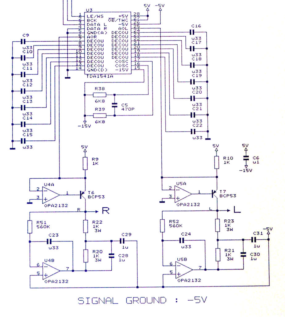
I used OP-amps in a dual DC servo circuit (attached picture).
It was used in the final TDA1541A projects SD2 and UD2.
Signal ground is connected to the -5V supply that serves as “ground reference”.
T6 and T7 are current buffers that feed I/V resistors R22 and R23. R20, R21, and C28 ... C30 serve as spectrum shapers (experimental). When spectrum shapers are not required, remove C28 … C30 and short circuit R20 and R21.
U4A and U5A are used as DC servo that keeps DC voltage at the TDA1541A output at zero.
U4B and U5B are used to keep DC voltage on the outputs at -5V. This way there is no DC between -5V “GND reference” and outputs so the coupling cap can be eliminated.
This circuit fully meets TDA1541A output compliance of +25mV and -25mV.
So, if one has the desire to maintain a given value (i.e. 12.5Ohm) of output voltage compliance, does that bring a 4x parallel AD844 i/v solution back to the table?
Anyone has done a comparison vs. transformer i/v, if likely in the simultaneous balanced mode?
If you read the post a few pages on from the one quoted by rbfw, you will see that ECD states that the sound is better with a higher I/V resistor.
Where is the filtering?
I did try an AD844 based I/V, taking the output from pin 5 buffered with OP627 and all I got was much high frequency rubbish superimposed on the the output signal. I think the AD844s were oscillating but I gave up and returned to pure resistor + transformer.
Post 5159 in its entirety.
And a slightly more recent
John changed his tune:
Building the ultimate NOS DAC using TDA1541A
Post 5279 and Lcsasazar's oscillogram above tends to disprove the claim that distortion massively increases at 0db unless the compliance target is adhered to.
Ups my fault. It should have been #5279 I referredJohn changed his tune:
Building the ultimate NOS DAC using TDA1541A
Post 5279 and Lcsasazar's oscillogram above tends to disprove the claim that distortion massively increases at 0db unless the compliance target is adhered to.
to. Here he clearly states, that it is not desirably to keep the +/- 25mV. Distortion rises , yes , but only marginally so.
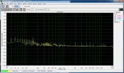
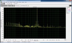
Attached my measurements. I/V resistor is 100R, bias resistor is 2k2 from +5V. Graph #1 is soundcard baseline, graph #2 is 1kHz sine 0dBfs. I haven't got any better soundcard at hand.
By the way, you should change your generator frequency, so you can avoid the spurious'es at 1000Hz multiples . I have the same problem with my measurement equipment, and therefore use 1200Hz instead.
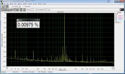
Here is the THD with my not-so-perfect sound card.
Excellent result so a thumbs up for the 100Riv resistor.
Are you using any particular type / brand?
Ups my fault. It should have been #5279 I referred
to. Here he clearly states, that it is not desirably to keep the +/- 25mV. Distortion rises , yes , but only marginally so.
There is what is said and there is what is done. Post 5530.
There is what is said and there is what is done. Post 5530.
There are so may examples of later posts where he recomends higher value I/V resistors.. This is one of the posts from last year..
Building the ultimate NOS DAC using TDA1541A
Indeed he does, objecting to the analytical sound he associates with lower i/v values or meeting compliance. Sounds like the path to audio hell to me. If I must suffer the TDA1541A I'll try and get hold of one the more exotic Marantz machines like the D1. In the meantime, I'll put the ones I have to good use driving a turntable.
Indeed he does, objecting to the analytical sound he associates with lower i/v values or meeting compliance. Sounds like the path to audio hell to me. If I must suffer the TDA1541A I'll try and get hold of one the more exotic Marantz machines like the D1. In the meantime, I'll put the ones I have to good use driving a turntable.
So you've never actually listened to any of the latest TDA1541a dac incarnations with for example, simultaneous mode, and/or balanced, and/or transformer output?
Dear 1541-ers, could you recommend a reliable source for low distortion sine wave (dithered) that is full scale digital 0....65535?
I have looked for a sig gen with a usb output but none exist (or would be affordable).
Nor can I find an ADC to connect to my old analogue sig gen.
Have you installed the VA software that Kolby provided a link to a few posts earlier?
The AD676 is a 16bit ADC with parallel output and its easy to convert the twc output to offset binary by inverting the MSB. Then it would require a shift register to convert this to serial and some glue logic to generate BCK & LE. Finally a low distortion analogue sine wave and a lpf at the input.
On the other hand, anyone conversant with DSPs could probably design something to do it all in the digital domain in 10 minutes.
Last edited:
- Home
- Source & Line
- Digital Line Level
- Building the ultimate NOS DAC using TDA1541A