THANKS!
But What I'm looking for is an ebook about dac and adc
wrote by RUDY JOHA N VAN DE PLASSCHE
Btw, the thing that I like the most with my setup is the incredible Stereo separation / Crosstalk. I've never experienced a more "channel silent" DAC like it is.
Setup:
Foobar(SOX@174kHz) > I2SoverUSB v.III > simultaneous > 2x TDA1541A > opamp I/V (ADA4898)
Reference:
Soekris dam1021 V.1 with Vref Caps increased to ~6000uF
Chi-Fi dual PCM1794A(mono) (all ADA4898)
Setup:
Foobar(SOX@174kHz) > I2SoverUSB v.III > simultaneous > 2x TDA1541A > opamp I/V (ADA4898)
Reference:
Soekris dam1021 V.1 with Vref Caps increased to ~6000uF
Chi-Fi dual PCM1794A(mono) (all ADA4898)
My circuit is best suited for balanced DAC output, you drive the ends of the center tapped primary of the transformer in opposite phase, so the -2mA bias currents cancel. One transformer and one tube per channel. The output is low impedance unbalanced.
I can see the appeal as a front and for a balanced system (if that's your preference). Do the 1541As need to be matched for any parameters, and is the 2H cancellation audibly apparent WRT a SE stage?
To run balanced and then recombine to SE seems counterintuitive to me.
I can also see the appeal (probably more than any other scenario involving the additional parts) of running a two way speaker, each driver bi-amped right the way back to independent dedicated HF and LF DACs using PC based software for crossover and DSP, each being optimised and BW limited for optimum performance.
Lots of cool stuff. Is there anything more linear than a resistor as IV ?
My circuit is best suited for balanced DAC output, you drive the ends of the center tapped primary of the transformer in opposite phase, so the -2mA bias currents cancel. One transformer and one tube per channel. The output is low impedance unbalanced.
You do still have I/V resistors?
Or no resistors and you have grounded the centre tap, in which case DC is flowing through the transformer? (not allowed for the Sowters)
I have tried my balanced setup with the centre tap grounded and not grounded and cannot hear a difference. (I have 100r I/V resistors)
For my opinion it is not good to put transformer directly on the current output of the TDA1541A dac chip. When You put the transformer IV conversion acting at the Rdc component of the transformer winding. And it is not common to find transformer with lower Rdc windings for smaller offset than stated in the datas, considering terms of lower distortion. Additionally if the Rdc winding of the transformer is low it could implicating a lower number of turns and leading to lower primary inductance... Can affect bandwidth in low end, and could be less capacitive to secondary, with corresponding lower number of turns. So it could have larger extennsin at the upper end...
.
Alzo should mind the total phase. If You put the +Io at the Riv You will get -Vo. And opposite.
.
The proper way is to use ballanced version. With Current injection of 2mA, and 2 x Riv-s. Connected from Io to GND chip each. THEN go to Inter-stage transformer.
At the Riv-s will be the some small offset BUT it is the same value. Connect now Vouts from Riv taps to the transformer. CT of the transformer leave unconnected. Do not connect CT tap to GND or elsewhere.
The transformer will be acting as isolating passive device, and because of the low value of present signal will have less self distortion. RC snubber network, at the secondary should check and implement if it is needed.
.
After that manage amplification of low level signal, phase at the output of the trafo, filtering of HF component, and output buffer if needed for lower output impedance.
For complete galvanic isolation use separate power supply from the mains point with separate powr transformer. If You have extra space it could be ddual mono 2 x independent PS units for each channel. That is almost ALL and Coul be implemented with all current output dac modules.
...
These higher amplifications gor my opinion should be done with tube of needed higher mju factor, correctly biased. Or JFET for little bit lower amplification result. For my opinion SE topology of amplification stage is better than PP complementary topology...
...
It is not bad idea to Add a for instance low impedance buffer after the IV R, If you want purist approach. That buffer could be supplied with +-15V of TDA1541A power branch. That way You can find more good options for the inter-stage transformer.
.
This is from personal praxis and listening experience.
Cheers
")
.
.
Alzo should mind the total phase. If You put the +Io at the Riv You will get -Vo. And opposite.
.
The proper way is to use ballanced version. With Current injection of 2mA, and 2 x Riv-s. Connected from Io to GND chip each. THEN go to Inter-stage transformer.
At the Riv-s will be the some small offset BUT it is the same value. Connect now Vouts from Riv taps to the transformer. CT of the transformer leave unconnected. Do not connect CT tap to GND or elsewhere.
The transformer will be acting as isolating passive device, and because of the low value of present signal will have less self distortion. RC snubber network, at the secondary should check and implement if it is needed.
.
After that manage amplification of low level signal, phase at the output of the trafo, filtering of HF component, and output buffer if needed for lower output impedance.
For complete galvanic isolation use separate power supply from the mains point with separate powr transformer. If You have extra space it could be ddual mono 2 x independent PS units for each channel. That is almost ALL and Coul be implemented with all current output dac modules.
...
These higher amplifications gor my opinion should be done with tube of needed higher mju factor, correctly biased. Or JFET for little bit lower amplification result. For my opinion SE topology of amplification stage is better than PP complementary topology...
...
It is not bad idea to Add a for instance low impedance buffer after the IV R, If you want purist approach. That buffer could be supplied with +-15V of TDA1541A power branch. That way You can find more good options for the inter-stage transformer.
.
This is from personal praxis and listening experience.
Cheers
.
Check out the ECs non inductive hand made Riv design. In this topic posted earlier. And consider Graphite hand made Riv also, for those lower values of Riv.
.
For the phase path from Riv to end:
+I@Riv, -Vout, SE amplification stage (tube or jfet), +Vout.
-I@Riv, +Vout, SE amplification stage (tube or jfet), -Vout.
.
For the phase path from Riv to end:
+I@Riv, -Vout, SE amplification stage (tube or jfet), +Vout.
-I@Riv, +Vout, SE amplification stage (tube or jfet), -Vout.
Last edited:
For my opinion it is not good to put transformer directly on the current output of the TDA1541A dac chip. When You put the transformer IV conversion acting at the Rdc component of the transformer winding. And it is not common to find transformer with lower Rdc windings for smaller offset than stated in the datas, considering terms of lower distortion. Additionally if the Rdc winding of the transformer is low it could implicating a lower number of turns and leading to lower primary inductance... Can affect bandwidth in low end, and could be less capacitive to secondary, with corresponding lower number of turns. So it could have larger extennsin at the upper end...
.
Alzo should mind the total phase. If You put the +Io at the Riv You will get -Vo. And opposite.
.
The proper way is to use ballanced version. With Current injection of 2mA, and 2 x Riv-s. Connected from Io to GND chip each. THEN go to Inter-stage transformer.
At the Riv-s will be the some small offset BUT it is the same value. Connect now Vouts from Riv taps to the transformer. CT of the transformer leave unconnected. Do not connect CT tap to GND or elsewhere.
The transformer will be acting as isolating passive device, and because of the low value of present signal will have less self distortion. RC snubber network, at the secondary should check and implement if it is needed.
.
After that manage amplification of low level signal, phase at the output of the trafo, filtering of HF component, and output buffer if needed for lower output impedance.
For complete galvanic isolation use separate power supply from the mains point with separate powr transformer. If You have extra space it could be ddual mono 2 x independent PS units for each channel. That is almost ALL and Coul be implemented with all current output dac modules.
...
These higher amplifications gor my opinion should be done with tube of needed higher mju factor, correctly biased. Or JFET for little bit lower amplification result. For my opinion SE topology of amplification stage is better than PP complementary topology...
...
It is not bad idea to Add a for instance low impedance buffer after the IV R, If you want purist approach. That buffer could be supplied with +-15V of TDA1541A power branch. That way You can find more good options for the inter-stage transformer.
.
This is from personal praxis and listening experience.
Cheers
.
Its not the way I do it, but each to his own.
Yes, balanced is the way to go, but also with an I/V resistor to generate the voltage for the transformers to work without them having DC flowing through. No need for current injection either with this method.
I personally favour no current injection, no additional filtering and definitely no active devices between transformer and power amp volume pot. This way there are far few opportunities to affect the sound otherwise you can spend forever tinkering with designs, component values etc.
You can fine tune the sound with the secondary load resistance. For example I have built an Aleph 5 single ended amp and the bass is much less than my Quad 405, which I put down to the A5 having only 10k input impedance, whilst my vol pot is 50k although I can't be sure its not the amp itself running too high volts and too low current for my 6R speakers.
Of course if your amp is not sensitive enough you will need additional amplification. Or two amps driven from the antiphase transformer outputs with the speakers connected in bridge mode. (would need a 4gang vol pot however)
I think that for the passive Riv You have to tap one end to ground - to have any conversion
In the direct Transformer load, You have I/V conversion at the highly reactive element. I listened more implementation like this and personally I was not satisfied. Most of them was from prominent brands. Modifying in this fashion i explained was significantly better. But I must say that was SE typologies? Cant remember now for sure...
.
For the passive IV conversion It is from significance to have "pure" resistive load. Like EC explained earlier on the topic. And give the option for the hand made Isotan wire resistor. I make it may self and it sound very good?
...
How was offset without current inj. and what value of Riv was in Your example please?
Cheers
.
Last edited:
You can fine tune the sound with the secondary load resistance. For example I have built an Aleph 5 single ended amp and the bass is much less than my Quad 405, which I put down to the A5 having only 10k input impedance, whilst my vol pot is 50k although I can't be sure its not the amp itself running too high volts and too low current for my 6R speakers.
If You are changing the value of input pot it can lead to cutting out highs at lower pot levels? Because of conjunction with dynamic capacitance of the stage?
But also, if this amp have C at the output to speaker - maybe should check this value against the load and increase it for lower LF rolloff?
I dont know exactly the case only thinking loudly...
I agree with much of what you say. PP 2H cancellation, and also output impedance issues.
Further, to say you have a passive output to your DAC and just to add an additional gain stage, or any stage thereafter to make up the shortfall is like putting the cart in front of the horse.
There are only a few current model DACs using 1541a, and they all run single ended and with resistor IV. Zanden, AMR, Audial.. but what do they know, right?
Consider the most simple set up. just an Riv and coupling C to output. It is not good idea because for larger output V You forced to use larger Riv value. That will lead to much higher offset then stated in datas. (Some of folks even measure that, me too...). And You will stay with increased distortion? So no matter is it SE or BAL topology of TDA1541A, and passive Riv, I think that lower value of Riv should be used. That will cause low Voltage signal level that should be amplify to reach some standard value.
...
Other thing is dac chip have DA grounds. For my op. it should be a galvanic isolated to make "pure" analog ground. Generally, transformers have significantly lower self distortion with lower value of signal...
...
I think that Zanden have some active circuit to drive passive notch filter multiply network? Please take a look at the Zanden papers? Also I think that Audial have also an active circuit to drive isolation transformer? In some models it have a active IV conversion even? I dont have these schs to check now.
...
There are many solutions for TDA1541A end stages.
cheers
Last edited:
Consider the most simple set up. just an Riv and coupling C to output. It is not good idea because for larger output V You forced to use larger Riv value. That will lead to much higher offset then stated in datas. (Some of folks even measure that, me too...). And You will stay with increased distortion? So no matter is it SE or BAL topology of TDA1541A, and passive Riv, I think that lower value of Riv should be used. That will cause low Voltage signal level that should be amplify to reach some standard value.
I don't think anyone is suggesting trying to achieve a suitable output voltage with a large value resistor and capacitor output. FFT analysis clearly shows 68 ohms as a sensible upper limit, and this has been covered many times now. I prefer 33 to 47 ohms.
Seems to me that overall THD level is perhaps not as critical as even to odd harmonic spectra, especially higher level harmonics, and this speaks also to my comment WRT 2H cancellation within balanced stages. This seems to be often overlooked, or misunderstood.
Other thing is dac chip have DA grounds. For my op. it should be a galvanic isolated to make "pure" analog ground. Generally, transformers have significantly lower self distortion with lower value of signal...
The digital and analogue grounds are shared at some point. I understand your comment about galvanic isolation, and this can be done also at the output of the analogue stage. Very generally WRT the transformer comment, certainly not compared with a resistor, and then I think overall context becomes important. Consider E280F or D3a as triodes, suitably loaded noise and distortion will be beyond concern, load it with a step down transformer and you have a gain stage, buffer, LP filter and galvanic isolation with the use of two resistors, one tube and one transformer.
I think that Zanden have some active circuit to drive passive notch filter multiply network? Please take a look at the Zanden papers? Also I think that Audial have also an active circuit to drive isolation transformer? In some models it have a active IV conversion even? I dont have these schs to check now.
Zanden 5000 uses a complicated filter, apparently to good effect, and I believe that with Fs 176kHz this becomes unnecessary anyway. Still the use of a resistor IV, you can use the output current of the 1541a, the mu of the tube, and the output voltage to determine what value of resistor this is.
WRT Audial, the use of OPA861 to rx the 1541a output current which is modulated by the Iq of approx 7mA then mirrored to the collector where a 1k5 resistor performs the IV conversion (4mA x 1k5 = 6vpp, or 2.1vRMS). Load to the 1541a at 7mA is approx 10 ohms. This resistor is then buffered by another opamp of the same type. The circuit uses current injection to null the offset to zero volts, in reality it is subject to minor thermal instability as expected. When nulled for zero at the output of the buffer, it can drive a 0mA type transformer, yet in my experience it does not respond well to direct inductive loading, I have lost a few to no apparent reason, and was surprised that things actually sounded better without the buffer and a series capacitor output in lieu of the transformer.
There are many solutions for TDA1541A end stages.
cheers
Indeed, and I have built variations of all mentioned within this post, with the exception of the zanden filter, and I know which I prefer - and as before, a lot will be subjective, but I think some understanding as to why, might assist the builder with a direction, or at least a starting point.
Kind regards HK
Last edited:
I think that for the passive Riv You have to tap one end to ground - to have any conversion
In the direct Transformer load, You have I/V conversion at the highly reactive element. I listened more implementation like this and personally I was not satisfied. Most of them was from prominent brands. Modifying in this fashion i explained was significantly better. But I must say that was SE typologies? Cant remember now for sure...
.
For the passive IV conversion It is from significance to have "pure" resistive load. Like EC explained earlier on the topic. And give the option for the hand made Isotan wire resistor. I make it may self and it sound very good?
...
How was offset without current inj. and what value of Riv was in Your example please?
Cheers
.
I use one 100R 1% metal film on each of the 4 dac outputs. (to ground)
There is no need to cancel the offset because the transformer is connected across the + & - Dac I/v resistors (which are both at -200mv no signal, so no DC current flows through the transformer)
I have tried connecting the centre tap to ground but as I said, I could not hear any difference, so its left unconnected and I also don't want another path to ground which is frequency dependent.
I will experiment with non inductive wire wound resistors.
Zanden 5000 uses a complicated filter, apparently to good effect, and I believe that with Fs 176kHz this becomes unnecessary anyway. Still the use of a resistor IV, you can use the output current of the 1541a, the mu of the tube, and the output voltage to determine what value of resistor this is.
WRT Audial, the use of OPA861 to rx the 1541a output current which is modulated by the Iq of approx 7mA then mirrored to the collector where a 1k5 resistor performs the IV conversion (4mA x 1k5 = 6vpp, or 2.1vRMS). Load to the 1541a at 7mA is approx 10 ohms. This resistor is then buffered by another opamp of the same type. The circuit uses current injection to null the offset to zero volts, in reality it is subject to minor thermal instability as expected. When nulled for zero at the output of the buffer, it can drive a 0mA type transformer, yet in my experience it does not respond well to direct inductive loading, I have lost a few to no apparent reason, and was surprised that things actually sounded better without the buffer and a series capacitor output in lieu of the transformer.
Indeed, and I have built variations of all mentioned within this post, with the exception of the zanden filter, and I know which I prefer - and as before, a lot will be subjective, but I think some understanding as to why, might assist the builder with a direction, or at least a starting point.
Kind regards HK
There are certainly almost infinite ways to recover the audio from the TDA1541 and everyone has there own preferred method. However just because xyz commerical manufacturer uses a particular method does not imply it must be superior.
Do these 'high end' manufacturers use simultaneous mode and stop the bit clock after latching the data? Or have they just focused on the reconstruction filter?
I don't have the means, money & time to explore all the various I/V stages so I have tried to eliminate all the variables surrounding current injection, opamps, tubes, interstage transformers etc by sticking to the simplest - passive I/V and a transformer designed for the job.
I am very pleased with the result and impressed with what is possible from a couple of TDA1541s.
The only commercial dacs I have owned over the years were a Pink Triangle Ordinal (TDA1547 DAC7 bitstrem dac), a Audio Note Dac 1.1 (AD1865 NOS + tube output) and a Musical Fidelity XRAY - (Burr Brown PCM dac).
I do remember removing the tube output of the DAC1.1 and fitting my transformers to the benefit of the SQ.
I don't have the means, money & time to explore all the various I/V stages so I have tried to eliminate all the variables surrounding current injection, opamps, tubes, interstage transformers etc by sticking to the simplest - passive I/V and a transformer designed for the job.
If they were designed for the job they would be gapped for 2mADC.
What is the output voltage at 0dB FS, and the output impedance at the output terminals?.
HK
Last edited:
Now I have modified my DAC/Preamp so it now consists of 2 TDA1541A in balanced simultaneous mode.I use one 100R 1% metal film on each of the 4 dac outputs. (to ground)
There is no need to cancel the offset because the transformer is connected across the + & - Dac I/v resistors (which are both at -200mv no signal, so no DC current flows through the transformer)
I have tried connecting the centre tap to ground but as I said, I could not hear any difference, so its left unconnected and I also don't want another path to ground which is frequency dependent.
I will experiment with non inductive wire wound resistors.
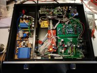
First picture is of the DAC/Preamp open, where you can see the dual TDA1541a board and the small Sowter transformers. The Preamp/vol consists of bruno putzeys balanced preamp with Maya controller. Inside is also a second DAC that eventually shall feed a subwoofersystem.
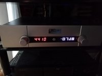
From the next picture, you can see the front with the leftside display displaying the sampling frequency.
I was a little disappointed by the sound at first especially when the digital signal was high.
The main difference between how the DAC was before the modification, besides the fact that it is now balanced, is that before I had to bias the output from the TDA1541A to avoid DC flowing through the transformers. This is not necessary when two outputs are feeding the transformer.
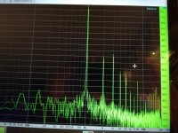
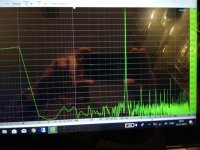
BUT! When the TDA 1541A is loaded by 100 Ohm and have no bias, the output is ca. -200mV DC and if you to that add the AC when outputting 0dB digital , the output peaks at around -400 mV and this is too much for the TDA1541A. It will start to increase distortion. I have attached two pics from a (pretty noisy) PC spectrum analyzer, The first is with no bias and the second is with 2 mA bias.
What I did was to remove the four 100 Ohm resistors and the transformers from the outputs, and connect a trimpot from +5V to one output and trim it to 0 V DC and the measure the value, just to be sure. It turned out to be near 2K4 witch I had in my collection. I then reinstalled the 100 ohm and connected each of those to a 2K4 going to +5V and then reconnected the transformers .
It is quite obvious that bias is indeed needed when operating the TDA1541A with a 100 Ohm I/V resistor. If you lower this value considerably, you can do without the bias.
Attachments
The I/V resistor is the cathode impedance of the tubes, reflected to the primary. The center tap of the primary is grounded, but the -2 mA bias current cancel each other in the two halves of the primary, because the DAC chips work in push-pull.You do still have I/V resistors?
Or no resistors and you have grounded the centre tap, in which case DC is flowing through the transformer? (not allowed for the Sowters)
I have tried my balanced setup with the centre tap grounded and not grounded and cannot hear a difference. (I have 100r I/V resistors)
I was a little disappointed by the sound at first especially when the digital signal was high.
The main difference between how the DAC was before the modification, besides the fact that it is now balanced, is that before I had to bias the output from the TDA1541A to avoid DC flowing through the transformers. This is not necessary when two outputs are feeding the transformer.
BUT! When the TDA 1541A is loaded by 100 Ohm and have no bias, the output is ca. -200mV DC and if you to that add the AC when outputting 0dB digital , the output peaks at around -400 mV and this is too much for the TDA1541A. It will start to increase distortion. I have attached two pics from a (pretty noisy) PC spectrum analyzer, The first is with no bias and the second is with 2 mA bias.
What I did was to remove the four 100 Ohm resistors and the transformers from the outputs, and connect a trimpot from +5V to one output and trim it to 0 V DC and the measure the value, just to be sure. It turned out to be near 2K4 witch I had in my collection. I then reinstalled the 100 ohm and connected each of those to a 2K4 going to +5V and then reconnected the transformers .
It is quite obvious that bias is indeed needed when operating the TDA1541A with a 100 Ohm I/V resistor. If you lower this value considerably, you can do without the bias.
Interesting. I will try your suggestion although I can't say I have heard any obvious distortion. (probably I wouldn't given its -54db)
I assumed that a load resistor on the secondary would reduce the primary impedance (to 65R claim Sowter) which is in parallel with the I/V resistor, so although the output is at -200mv with no signal, at frequencies above about 10Hz, the 1541 sees a much lower resistance.
- Home
- Source & Line
- Digital Line Level
- Building the ultimate NOS DAC using TDA1541A