...but up until now only in single ended mode. I am planning to use TDA1541 in balanced mode at a later time and with battery PS..
Pg 650, post #6492, you said you were using 1541A in balanced mode?

Last edited:
Sowter 1495?
No, 1465 is the one that replaces mine which was a 9545. Not sure what the difference is.
Maybe the 1495 could be used but you'll need to ask Sowter. I see its half the price of the 1465.
I can second batterymans observations on the Sowter transformers. They really shine when used with TDA1541 in NOS mode.
I also use TDA1541 in simultanious mode and with 50 Hz DEM, but up until now only in single ended mode. I am planning to use TDA1541 in balanced mode at a later time and with battery PS..
The sooner you switch to balanced, the sooner you will hear the benefit of the transformers!
I look forward to your comments on battery power.
(ps you can have one of my new boards foc, when I get round to finishing the design, as can the others. See post 6826)
Well and this was true, but it was NOT with the sowter transformers!!!Pg 650, post #6492, you said you were using 1541A in balanced mode?
When I purchased the sowter transformers I wanted to try them against my previous reference setup (balanced TDA1541a wit active I/V converter) to get an idea how it would fair against that, and it was so good , even with only one TDA1541A that I haven't yet tried the sowter with two TDA1541A. So no need for
Thx, but I already have two of your previous boards. It is actually one of them I use with the sowter , so it will be quite easy to populate the other half to make it balanced. The reason I have two of your boards is , that I would ultimately like to run the TDA1541A in balanced signed magnitude mode and this calls for 4 TDA1541A..The sooner you switch to balanced, the sooner you will hear the benefit of the transformers!
I look forward to your comments on battery power.
(ps you can have one of my new boards foc, when I get round to finishing the design, as can the others. See post 6826)
Of course a fully passive aproach is the best, but for me it was just too expensive (student). I had very good results with this discrete i/v : http://lampizator.eu/LAMPIZATOR/FETISHIZATOR/JFET_CDout.pdf
But you need a very good psu for this one.
But you need a very good psu for this one.
Well and this was true, but it was NOT with the sowter transformers!!!
When I purchased the sowter transformers I wanted to try them against my previous reference setup (balanced TDA1541a wit active I/V converter) to get an idea how it would fair against that, and it was so good , even with only one TDA1541A that I haven't yet tried the sowter with two TDA1541A. So no need for
Easy to get confused, thanks for the clarification. How were you dealing with the 2mA offset current when used with single 1541A, and what then is the output impedance of the DAC with the step up transformer with resistor across the secondary (what value of resistor is required for something close to 2vRMS output) ?.
No problem.Easy to get confused, thanks for the clarification. How were you dealing with the 2mA offset current when used with single 1541A, and what then is the output impedance of the DAC with the step up transformer with resistor across the secondary (what value of resistor is required for something close to 2vRMS output) ?.
I use a resistor to +5V supply trimmed to 0 Vdc at the output of the TDA 1541A.
The output impedance of the DAC is irrelevant, but the load impedance is important as this should be as low as possible, but to get a reasonable output level, you have to make a compromise here and it depends on what you use as buffer/amp after the transformer. I use this BPPBP - Bruno Putzey's Purist Balanced Preamp (well a balanced volume control really)
after the transformer ..
Sowter has a good calculator here:
DAC I/V CONVERSION OUTPUT TRANSFORMERS
I think 2 V rms is too much to expect directly from the trafo.
If the output voltage after the transformer is too low, use a hybrid (passive/active) solution:
Laszlo's Valve Output Stage with Lundahl transformer
Laszlo's Valve Output Stage with Lundahl transformer
No problem.
The output impedance of the DAC is irrelevant, but the load impedance is important as this should be as low as possible, but to get a reasonable output level, you have to make a compromise here...
I think 2 V rms is too much to expect directly from the trafo.
I was meaning what is the output impedance at the output connectors of the DAC system (if we consider it as a stand alone functional component), in other words the output impedance at the secondary of the transformer, across the IV resistor?.
In a practical sense does it lock you into high impedance loads (the input impedance of whatever stage follows) and potential HF roll off in conjunction with interconnecting cable capacitance?
The reason I ask is that I get 2vRMS at 600 ohm output impedance with a low noise tube, two low value resistors, and a 2:1 output transformer. It fully accepts the offset current of the 1541a, doesn't require a buffer, is all in one unit, and can drive a 10k load without problems.
Last edited:
I was meaning what is the output impedance at the output connectors of the DAC system (if we consider it as a stand alone functional component), in other words the output impedance at the secondary of the transformer, across the IV resistor?.
In a practical sense does it lock you into high impedance loads (the input impedance of whatever stage follows) and potential HF roll off in conjunction with interconnecting cable capacitance?
The reason I ask is that I get 2vRMS at 600 ohm output impedance with a low noise tube, two low value resistors, and a 2:1 output transformer. It fully accepts the offset current of the 1541a, doesn't require a buffer, is all in one unit, and can drive a 10k load without problems.
You can have a resistor on either the secondary or primary side of the trafo, and this determines the loading of the DAC chip. If you place it on the secondary side , you have an impedance transformation ratio in the trafo.
If you want 2V rms out of the trafo , it is of course at an elevated impedance level ,if you want to keep the TDA1541,s output at a resonable level.
I would recommend some sort of amplification or buffering after the trafo, before driving a cable to the poweramp. But it very much depends on your actual setup. If you plan to place the DAC inside the poweramp, the buffer could be avoided.
Of course your active stage does not need a buffer.
One of the benefits of the trafo is in fact that it acts as a low pass filter and this is beneficial in a NOS DAC.
The solution lcsaszar suggests is very interesting, even though I would need two transformers and two tubes, as I am using a balanced system ...
I'm fortunate in that my Quad 405 is more sensitive than modern power amps so no additional amplification is needed. Indeed, I would have increased it's gain rather than install any sort of preamp or buffer.
With dual balanced dacs, you do of course, have double the voltage swing for the same 100R I/V resistors, which is another reason for going balanced.
With a 50k Alps pot between Dac and 405, going beyond 50% is too loud. (89db/1watt speakers)
With dual balanced dacs, you do of course, have double the voltage swing for the same 100R I/V resistors, which is another reason for going balanced.
With a 50k Alps pot between Dac and 405, going beyond 50% is too loud. (89db/1watt speakers)
Thx, but I already have two of your previous boards. It is actually one of them I use with the sowter , so it will be quite easy to populate the other half to make it balanced. The reason I have two of your boards is , that I would ultimately like to run the TDA1541A in balanced signed magnitude mode and this calls for 4 TDA1541A..
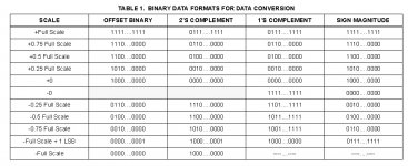
What advantage does signed magnitude give over offset binary and how will you produce it?
According to Intersils'c table below, it appears that 0 can be 1000.000 or 000.000 so presumably the changing of the MSB at zero signal levels gives some audible benefits? (how do you hear them if the signal amplitude is zero. since once it increases even by '1' the msb is either 0 or 1)
Attachments
Last edited:
Dear all:
I've seen an ebook about the 14 16bit dac and dem by philips here
But I just can't find it.
Do anyone know which floor it is?
There is some info here:
Philips TDA1541A d/a converter - DutchAudioClassics.nl
and here:
TDA1541A
THANKS!
But What I'm looking for is an ebook about dac and adc
wrote by RUDY JOHA N VAN DE PLASSCHE
I've read the one you mean. Try this:
Found it.
Attachments
Last edited:
My circuit is best suited for balanced DAC output, you drive the ends of the center tapped primary of the transformer in opposite phase, so the -2mA bias currents cancel. One transformer and one tube per channel. The output is low impedance unbalanced.The solution lcsaszar suggests is very interesting, even though I would need two transformers and two tubes, as I am using a balanced system ...
- Home
- Source & Line
- Digital Line Level
- Building the ultimate NOS DAC using TDA1541A