I think I pointed you in that direction in post 6631:
Building the ultimate NOS DAC using TDA1541A
Not specifically and indeed nor did Ian himself and then we all got bogged down in discussions of whether the LSB was being missed. Which again, no one has proved by actual measurements of the dac output.
Anyway, I've just ordered a FifoII and clock board from Ian and he has very kindly agreed to replace the I2S board I damaged, for a few Dollars.
The FIFO board can accept other formats than I2S so I can use my preferred Denon rack mounting professional cd player as a transport. (I like the all steel construction, solid feel to the buttons and sturdy mechanism. (Sanyo)
DUAL TDA1541 WORKING WITH IAN'S BOARDS.
I eventually damaged my first I2S-PCM board by connecting to 15v instead of 5v. Ian very generously replaced it for the cost of the cost of repair.
I also then bought a Fifo 2 and dual clock board.
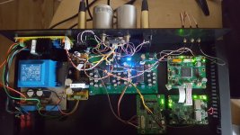
Today it is all connected and it sounds superb. Better than the dual AD1862 I have been listening to in the meanwhile (via SPDIF and a SRC4192 EV).
I/V is four 50R resistors and the Sowter transformers. By using balanced operation, the static 2ma offset of the dacs is nullified so no DC flows through the transformers which si essential.
The wiring needs tidying and my MK2 dac pcb will have pads for U/fl connectors for the data but I am relieved I now have something great to listen with.
Not specifically and indeed nor did Ian himself and then we all got bogged down in discussions of whether the LSB was being missed. Which again, no one has proved by actual measurements of the dac output.
Anyway, I've just ordered a FifoII and clock board from Ian and he has very kindly agreed to replace the I2S board I damaged, for a few Dollars.
The FIFO board can accept other formats than I2S so I can use my preferred Denon rack mounting professional cd player as a transport. (I like the all steel construction, solid feel to the buttons and sturdy mechanism. (Sanyo)
I eventually damaged my first I2S-PCM board by connecting to 15v instead of 5v. Ian very generously replaced it for the cost of the cost of repair.
I also then bought a Fifo 2 and dual clock board.
Today it is all connected and it sounds superb. Better than the dual AD1862 I have been listening to in the meanwhile (via SPDIF and a SRC4192 EV).
I/V is four 50R resistors and the Sowter transformers. By using balanced operation, the static 2ma offset of the dacs is nullified so no DC flows through the transformers which si essential.
The wiring needs tidying and my MK2 dac pcb will have pads for U/fl connectors for the data but I am relieved I now have something great to listen with.
Attachments
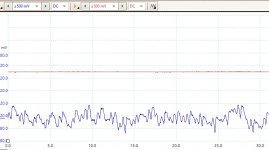
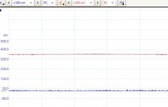
Very clean differential traces from the left channel dac D+/D- taken directly from across the dac audio out pins. (loaded with the I/V resistors and transformer)
These I believe shows the benefits of balanced simultaneous operation and the clock stopping features of Ian's board.
Who needs OS with such clean signals!
Blue = signal and then no signal.
These I believe shows the benefits of balanced simultaneous operation and the clock stopping features of Ian's board.
Who needs OS with such clean signals!
Blue = signal and then no signal.
Attachments
I want to use LiFePO4 batteries to power my 1541a DAC but the voltage for a single cell is 3.3V so the +/- 5V would be +/- 6.6v and the -15 V would be - 16.5 V.
The max. in the data sheet is +/- 5.5 V and - 16V and the absolute max +/- 7 V and -17 V.
Will it be too dangerous to use the LiFePO4 voltage levels for the TDA1541A?
The max. in the data sheet is +/- 5.5 V and - 16V and the absolute max +/- 7 V and -17 V.
Will it be too dangerous to use the LiFePO4 voltage levels for the TDA1541A?
Hello batteryman what sowter model are you using?I eventually damaged my first I2S-PCM board by connecting to 15v instead of 5v. Ian very generously replaced it for the cost of the cost of repair.
I also then bought a Fifo 2 and dual clock board.
Today it is all connected and it sounds superb. Better than the dual AD1862 I have been listening to in the meanwhile (via SPDIF and a SRC4192 EV).
I/V is four 50R resistors and the Sowter transformers. By using balanced operation, the static 2ma offset of the dacs is nullified so no DC flows through the transformers which si essential.
The wiring needs tidying and my MK2 dac pcb will have pads for U/fl connectors for the data but I am relieved I now have something great to listen with.
Hello batteryman what sowter model are you using?
I'm using the 9545 but they have been superceded by 1465 although the specs seem the same.
DAC I/V CONVERSION OUTPUT TRANSFORMERS
I want to use LiFePO4 batteries to power my 1541a DAC but the voltage for a single cell is 3.3V so the +/- 5V would be +/- 6.6v and the -15 V would be - 16.5 V.
The max. in the data sheet is +/- 5.5 V and - 16V and the absolute max +/- 7 V and -17 V.
Will it be too dangerous to use the LiFePO4 voltage levels for the TDA1541A?
You may get away with it if you put heatsinks on the dacs, or maybe a series diode to lose 0.6v but this may negate the benefit of the batteries.
I'd measure the actual voltage with s simulated load as mine were about 3.4v.
Also, I've seen some dac schematics where the designer had fitted a 10R resistor in each supply lead close to the dac but before the decouplig caps. This would give you a 250 - 350mv margin.
I have some Lipo batteries (RC model 3.7v batteries) which I might try with my on board Dexa regulators, a pair gives about 7.6v and 5, will give 18.5v.
I like the idea of completely separate batteries for each supply.
Ian just answered my question regarding a silicon diode in series with the batteries, and he said it was worth a try, and his only concern was noise from the diode and suggested a capacitor in parallel with it to eliminate that.You may get away with it if you put heatsinks on the dacs, or maybe a series diode to lose 0.6v but this may negate the benefit of the batteries.
I'd measure the actual voltage with s simulated load as mine were about 3.4v.
Also, I've seen some dac schematics where the designer had fitted a 10R resistor in each supply lead close to the dac but before the decouplig caps. This would give you a 250 - 350mv margin.
I have some Lipo batteries (RC model 3.7v batteries) which I might try with my on board Dexa regulators, a pair gives about 7.6v and 5, will give 18.5v.
I like the idea of completely separate batteries for each supply.
Hi koldby,
Diode will increase the power supply impedance by roughly 1 Ohm.
TDA1541A datasheet specs:
+5V supply, 4.5V ... 5.5 typical, 7V limit, 27mA typical.
-5V supply, -4.5V ... -5.5V typical, -7V limit, 37mA typical.
-15V supply, -14V ... -16V typical, -17V limit, 25mA typical.
Operating TDA1541A beyond limiting values will permanently damage the chip.
3.3V LiFePO4 battery voltage can vary between approx. 1.8V and 3.4V. Typical voltage will be 3.3V
When connecting two of these batteries in series and use a series diode we get between 6 and 6.2V.
For the -15V we can use 3V7 Lithium Polymer batteries. These have 4.2V max. and 3.7V typical.
With 4 of these batteries in series plus a series diode we get max. voltage of 16.2V and typical voltage of 14.2V.
This is within limiting values but slightly exceeds typical values.
When placing (Lithium) batteries in series, balancing circuits are required.
Some more information here:
http://sound.whsites.net/articles/lithium-charging.htm
How critical is this range? I mean -13.5V is set in some Marantz/Philips players, and the -5V is set at -6V, is there any reason? .-15V supply, -14V ... -16V typical, -17V limit, 25mA typical.
Hi koldby,
Diode will increase the power supply impedance by roughly 1 Ohm.
TDA1541A datasheet specs:
+5V supply, 4.5V ... 5.5 typical, 7V limit, 27mA typical.
-5V supply, -4.5V ... -5.5V typical, -7V limit, 37mA typical.
-15V supply, -14V ... -16V typical, -17V limit, 25mA typical.
Operating TDA1541A beyond limiting values will permanently damage the chip.
3.3V LiFePO4 battery voltage can vary between approx. 1.8V and 3.4V. Typical voltage will be 3.3V
When connecting two of these batteries in series and use a series diode we get between 6 and 6.2V.
For the -15V we can use 3V7 Lithium Polymer batteries. These have 4.2V max. and 3.7V typical.
With 4 of these batteries in series plus a series diode we get max. voltage of 16.2V and typical voltage of 14.2V.
This is within limiting values but slightly exceeds typical values.
When placing (Lithium) batteries in series, balancing circuits are required.
Some more information here:
Lithium Cell Charging
Thanks for the response.
I see no reason to use Litium polymer instead of LiFePO4 and I believe the LiFePO4 is a more stable and easy battery to deal with than Litium Polymer batteries. Keeping LiFePO4 between 3.2V and 3.0V seams to be quite easy, as it is only a fully charged battery that starts @ 3.3V:
How to charge Lithium Iron Phosphate lithium ion battery packs including packs with high current and High Capacity.
So if the charger is set to stop charging a little before fully charged the voltages will be +/- 6.4V and - 16V without the diode and this should be within the safe region for the TDA1541A .
Maybe a circuit that starts discharging the batteries to the 3.2V level before making the connection to the DAC would be an option to reduce the risk of damaging the TDA1541A ?
When placing (Lithium) batteries in series, balancing circuits are required.
Some more information here:
Lithium Cell Charging
Thanks for the link - interesting.
However I wonder what the situation is as regards the multicell batteries - ie the RC model Lipo batteries that are available in voltages upto 22.2v and more?
Can we assume they have the necessary balancing circuitry built in as most seem to have just a 2 wire connection so there is no way for a charger to monitor (or control) the charging of each cell within the pack?
Or (more likely) the cheap ones from the usual source, do not.
Can we assume they have the necessary balancing circuitry built in as most seem to have just a 2 wire connection so there is no way for a charger to monitor (or control) the charging of each cell within ...
No, balancing is done within the charger and not in the battery itself. If you have a balanced battery pack it mostly has two connectors, one with thick wires for charging / discharging purposes and one with much smaller wire diameter for balancing.
Ones more : Stay with LiFePo4, plz. Lipo can be quite dangerous if not done properly and there are chemical differences that are also in favor for LiFePo4.
I run ma TDA1541A only with LiFePo4 direct power. It is by far superior to any psu i used up to date and very simple to achive. The chip itself runs at 6V - 6.6V without problems and -15 is -15V to -16.5V here without any problems. But i use my own charging/shutdown circuit, that keeps the batteries between 3.0 and 3.3V. I charge them only up to 3.3V with CV until i reach low charging current. I skip the CC step, this is slower, but it makes the charging much easier and more controlled. Of course the charging current still has a limit (1.5A in m case), so CV is enough, because i can never reach currents over the maximum for my batteries (3A max).
By the way, i dont use opamps, but a discrete output stage and this simply rocks on battery power, stunning compared to psu. Even opamps were very nice on battery (i used lme49710s).
The trick here is to run PURE battery, not to use 22V and regulate it down. The regulator will destroy the transient response, that makes the LiFePo4s so valueable. As soon as you use regulators, forget batteries, because you destroy their strenght (miliohms of internal resistance).
Last edited:
Thanks very nice to hear from someone who actually have tried LiFePO4 and TDA 1541A and , yes you need a balancing circuit with series connected LiFePO4 batteries, but, AFAIK only when charging.No, balancing is done within the charger and not in the battery itself. If you have a balanced battery pack it mostly has two connectors, one with thick wires for charging / discharging purposes and one with much smaller wire diameter for balancing.
Ones more : Stay with LiFePo4, plz. Lipo can be quite dangerous if not done properly and there are chemical differences that are also in favor for LiFePo4.
I run ma TDA1541A only with LiFePo4 direct power. It is by far superior to any psu i used up to date and very simple to achive. The chip itself runs at 6V - 6.6V without problems and -15 is -15V to -16.5V here without any problems.
By the way, i dont use opamps, but a discrete output stage and this simply rocks on battery power, stunning compared to psu. Even opamps were very nice on battery (i used lme49710s).
The trick here is to run PURE battery, not to use 22V and regulate it down. The regulator will destroy the transient response, that makes the LiFePo4s so valueable. As soon as you use regulators, forget batteries, because you destroy their strenght (miliohms of internal resistance).
No, balancing is done within the charger and not in the battery itself. If you have a balanced battery pack it mostly has two connectors, one with thick wires for charging / discharging purposes and one with much smaller wire diameter for balancing.
Ones more : Stay with LiFePo4, plz. Lipo can be quite dangerous if not done properly and there are chemical differences that are also in favor for LiFePo4.
I run ma TDA1541A only with LiFePo4 direct power. It is by far superior to any psu i used up to date and very simple to achive. The chip itself runs at 6V - 6.6V without problems and -15 is -15V to -16.5V here without any problems.
By the way, i dont use opamps, but a discrete output stage and this simply rocks on battery power, stunning compared to psu. Even opamps were very nice on battery (i used lme49710s).
The trick here is to run PURE battery, not to use 22V and regulate it down. The regulator will destroy the transient response, that makes the LiFePo4s so valueable. As soon as you use regulators, forget batteries, because you destroy their strenght (miliohms of internal resistance).
Thanks for that advice. I think I will do likewise and use directly connected LiFePo4 cells.
I use transformer I/V so no opamps and will be interested find out what difference batteries make to the already excellent sound quality using Dexa low noise regulators and IanCanada's boards.
(see post #6782 for photo)
Thanks very nice to hear from someone who actually have tried LiFePO4 and TDA 1541A and , yes you need a balancing circuit with series connected LiFePO4 batteries, but, AFAIK only when charging.
Yes, its nearly impossible that single cells will fall under their dangerous voltage of 2V when in series. I go to recharge if they fall under 15V (3V * 5). I dont care if one cell is at 2.9V and another at 3.1V. They get balanced the next time i charge.
During firsts test i monitored all cells and drift never exceeded 0.2V, so no problem.
Thanks for that advice. I think I will do likewise and use directly connected LiFePo4 cells.
I use transformer I/V so no opamps and will be interested find out what difference batteries make to the already excellent sound quality using Dexa low noise regulators and IanCanada's boards.
(see post #6782 for photo)
Yes, Ians Boards rock, thats true, but even Ian is experimenting with pure LIFEPO4s at the moment. Yesterday i saw a thread by him with a complex LiFePo4 charger with a very „pure battery power“ approach.
Of course you can build a psu with very simmilar or perhaps a bit better mesurements, but never for a comparable price. Batteries are the way to go if you dont want to spend much money on psus.
You can do without a balancing module if you use a charge module like this for each cell. When you want to play music , use relays to switch from the charger module to the DAC:Thanks for that advice. I think I will do likewise and use directly connected LiFePo4 cells.
I use transformer I/V so no opamps and will be interested find out what difference batteries make to the already excellent sound quality using Dexa low noise regulators and IanCanada's boards.
(see post #6782 for photo)
Mini USB TP5000 3.2V LiFePO4 Battery Charging Board Protection Charger Module | eBay
You can do without a balancing module if you use a charge module like this for each cell. When you want to play music , use relays to switch from the charger module to the DAC:
Mini USB TP5000 3.2V LiFePO4 Battery Charging Board Protection Charger Module | eBay
Nice module (Top price !). Do you use this module ? This is of course the easiest way, only question is, what is the voltage the module charges the batteries to ? I had two china modules that charged the lifepo4 up to 3.6V (Of course, they fall down to 3.4-3.5V very fast, but this could become problematic with the 5 battery series for -15V. In my case the fully charged voltage would be 1V higher than with 3.3V charged batteries.
No I have not tried it. This is even better priced:Nice module (Top price !). Do you use this module ? This is of course the easiest way, only question is, what is the voltage the module charges the batteries to ? I had two china modules that charged the lifepo4 up to 3.6V (Of course, they fall down to 3.4-3.5V very fast, but this could become problematic with the 5 battery series for -15V. In my case the fully charged voltage would be 1V higher than with 3.3V charged batteries.
Tp5000 3.6v 4.2v 2a Charging Charger Board for 3.2v Lifepo4 3.7v Lithium Battery | eBay
I would , for security make a circuit that discharged the batteries to a safe voltage before connecting to the TDA1541A
- Home
- Source & Line
- Digital Line Level
- Building the ultimate NOS DAC using TDA1541A