I mentioned this issue of the LSB with Ians pcb for the 1541 a few years back. In the end I thought it wasn't a problem because it sounded so much better than i2s. All this time I was actually listening to a 15bit dac. ...until EC came along and shared his circuit.
...until EC came along and shared his circuit. Hi Fellas,
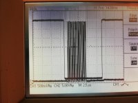
Dont mean to litter the forum with scope shots, but just wondering what exactly is going on here (aside from the noise from BCK on the Analog outputs) It looks like the sample starts before the least significant bit is clocked in? According to the data sheet (TDA1541A) this shouldn't be so - Unless i'm not clear about something.
Also notice how much BCK is visible on the Analog outputs without I2S attenuation - Hope to change that soon.
Bandwidth limited,
Top trace is BCK using only 50mhz probe - hence the slow rise time.
Bottom trace 11025hz square wave at full scale current output.
Simultaneous mode.
Ryan
A crude way would be a monostable and gate to simply delay the leading edge of LE by about 2clock periods - ie 1.4us, (and also to invert CLK)
I just got an idea to make it easy to get Ians coverter to work as it should, and went into the lab. to test it.
What about using the LE (or word clk ) input to Ians board as LE to the TDA1541A
See the picture.
It looks as if this would work just perfectly. You still have to invert the CLK of course.
I am sure some of the clever heads in this thread will correct me , if I am wrong
Attachments
Hi batteryman.
Ian may not have designed this converter to be compatible with the TDA1541A like rfbrw mentioned, but for other D/A converter chips like the AD1865 for example.
AD1865 clocks in data on the -rising- edge of BCK and this is exactly what Ians converter does, so nothing wrong here.
AD1865 latches its outputs on the -falling- edge of LE, Ians decoder also generates this signal correctly.
Just have a look at AD1865 datasheet page 7, this should clear things up.
TDA1541A just happens to clock in data on the falling edge of BCK and latches its outputs on the rising edge of LE, just the other way around. TDA1541A doesn't like it when LE changes state while data is still being clocked in either.
So if we want to drive a TDA1541A (SIM) with Ian's converter, we have to use some glue logic to make it work.
> BCK has to be inverted.
> LE signal has to be modified like i described in post #6630.
Yes, looks like Ian has got it wrong but will inverting BCK do anything to cure the peak break up?
Ian may not have designed this converter to be compatible with the TDA1541A like rfbrw mentioned, but for other D/A converter chips like the AD1865 for example.
AD1865 clocks in data on the -rising- edge of BCK and this is exactly what Ians converter does, so nothing wrong here.
AD1865 latches its outputs on the -falling- edge of LE, Ians decoder also generates this signal correctly.
Just have a look at AD1865 datasheet page 7, this should clear things up.
TDA1541A just happens to clock in data on the falling edge of BCK and latches its outputs on the rising edge of LE, just the other way around. TDA1541A doesn't like it when LE changes state while data is still being clocked in either.
So if we want to drive a TDA1541A (SIM) with Ian's converter, we have to use some glue logic to make it work.
> BCK has to be inverted.
> LE signal has to be modified like i described in post #6630.
Hi batteryman.
Ian may not have designed this converter to be compatible with the TDA1541A like rfbrw mentioned, but for other D/A converter chips like the AD1865 for example.
AD1865 clocks in data on the -rising- edge of BCK and this is exactly what Ians converter does, so nothing wrong here.
AD1865 latches its outputs on the -falling- edge of LE, Ians decoder also generates this signal correctly.
Just have a look at AD1865 datasheet page 7, this should clear things up.
TDA1541A just happens to clock in data on the falling edge of BCK and latches its outputs on the rising edge of LE, just the other way around. TDA1541A doesn't like it when LE changes state while data is still being clocked in either.
So if we want to drive a TDA1541A (SIM) with Ian's converter, we have to use some glue logic to make it work.
> BCK has to be inverted.
> LE signal has to be modified like i described in post #6630.
There is a specific OB jumper on the board specifically for use with the 1541 and connection diagrams for normal and a pair in balanced, but he seems to have overlooked the difference between it and the other dac chips.
What do you think of inverting BCK and then using Koldby's suggestion of feeding LE from the board's input, bypassing the board?
Now, correcting these shortcomings may improve the sound, but may not explain the distortion on peaks but would the wrong format? E.g.right justified, or normal pcm, not I2S
I have read that that Ians PCM board doesn't work quite right with TDA1541A, that it does function but results in 15bit performance. No doubt many of you have heard/read the same.
Perhaps this can be fixed with a firmware upgrade to Ians board (I2S to PCM for use with TDA1541A), perhaps Ian can, and will assist.
To batteryman, I have experienced what you speak of, and it presented in the same way. In my instance it was the peak to peak signal waveform was crashing into the DC rail voltage.
With hope that it all works out.
Hanze.
Last edited:
Definitely. It should be an easy fix for Ian if he wants to fix it.
Yes, it does explain it. Again, MSB, hint, hint...
Now, correcting these shortcomings may improve the sound, but may not explain the distortion on peaks but would the wrong format? E.g.right justified, or normal pcm, not I2S
Yes, it does explain it. Again, MSB, hint, hint...
Definitely. It should be an easy fix for Ian if he wants to fix it.
Yes, it does explain it. Again, MSB, hint, hint...
I believe that Ian is a good guy, he has offered much and tailored to the individual, and has delivered.
It should be a 'walk in the park' for him to address this issue.
Hanze.
Last edited:
Sure it would be no problem to fix that on NEW i2stopcm boards, but all the boards that has been sold to people , that wants to use them with TDA1541A , must use a hardware fix.I believe that Ian is a good guy, he has offered much and tailored to the individual, and has delivered.
It should be a 'walk in the park' for him to address this issue.
Hanze.
It is not as difficult as it sounds, though. I believe the solution I suggested in post #6662 will be an easy fix and even be better, as the LE transition is many clk cycles after the clk to TDA1541A has stopped.
Definitely. It should be an easy fix for Ian if he wants to fix it.
Yes, it does explain it. Again, MSB, hint, hint...
That's what I thought, but there was a suggestion it was not Ian's board but the wrong data format........
I didn't accept that as it is only the peaks that cause the distortion - ie when the MSB switches.
Also, regarding comments that the LSB isn't significant and you cannot hear the difference between 14 and 15 bits, surely, the LSB is set for every odd numbered value from 1 to max so you cannot just dismiss it. MSB -1 you could if you accepted a resolution reduction.
I'm sure we'll hear from Ian about a firmware update soon.
Sure it would be no problem to fix that on NEW i2stopcm boards, but all the boards that has been sold to people , that wants to use them with TDA1541A , must use a hardware fix.
It is not as difficult as it sounds, though. I believe the solution I suggested in post #6662 will be an easy fix and even be better, as the LE transition is many clk cycles after the clk to TDA1541A has stopped.
This certainly avoids having to ship the board back to Ian with postage costs for both parties (Ian ought to pay his customers shipping though)
I'll try the hardware fix this weekend and report back.
I think you have this the wrong way around. MSB is the Most Significant Bit and it is mandatory. LSB is the 24th bit in a 24 bit long bit stream and the 16th bit in a 16 bit long bit stream. If you discard 1 lsb from a 16 bit word, you get a 15 bit word. You loose resolution though.That's what I thought, but there was a suggestion it was not Ian's board but the wrong data format........
I didn't accept that as it is only the peaks that cause the distortion - ie when the MSB switches.
Also, regarding comments that the LSB isn't significant and you cannot hear the difference between 14 and 15 bits, surely, the LSB is set for every odd numbered value from 1 to max so you cannot just dismiss it. MSB -1 you could if you accepted a resolution reduction.
I'm sure we'll hear from Ian about a firmware update soon.
I think you have this the wrong way around. MSB is the Most Significant Bit and it is mandatory. LSB is the 24th bit in a 24 bit long bit stream and the 16th bit in a 16 bit long bit stream. If you discard 1 lsb from a 16 bit word, you get a 15 bit word. You loose resolution though.
Yes, I know that, I just didn't make myself very clear!
Well you are right so long as you will always have a LSB in a binary word. Its the wordlength you reduce....
The misunderstanding arises from the fact that it is the last data bit in the serial stream you discard and this was formerly the LSB. The new LSB will be the last in the new , reduced length, data stream.
The misunderstanding arises from the fact that it is the last data bit in the serial stream you discard and this was formerly the LSB. The new LSB will be the last in the new , reduced length, data stream.
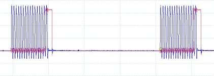
SCREEN SHOTS FROM USB I2S ADAPTOR
Koldby, tried your suggestion of bypassing Ian's board for WS - no difference to the distortion.
Next connected the board to a cheap USB to I2S interface.
Screen shots attached. Still looks like one of the clock cycles is after the rising edge of LE but no distortion heard from Youtube so far. (48Khz)
Does this mean that the I2S data from the Denon Cd player is not actually I2S?
Images: Bck + L, D + BCK, D + L
Attachments
Ian's board operation
Hi Everyone,
I've been using Ian's boards (SPDIF+FIFO+I2stopcm) with a Red Baron5 TDA1541A (in offset binary mode) and watching this thread with high interest. I'm not a dac guru so the theoretical parts are interesting for me but I'm far from interrupting the discussion. I've never heard that kind of distortion which has been described here. So i would like to get know whether I could catch that distortion in my system or not.
When I assembled my dac, I heard a Madonna Hard candy titled disc (I'm an old fashioned guy listen to CD discs via Micromega Duo spinner) and its last song, the Voices was very distorted and I thought that was something wrong. I have an oscilloscope and I checked the analog signal - and that reached the upper and lower limits. I also checked the analog signal with a stock dvd player and the signal was also from the bottom and to the top - so I realized that this song is deliberately recorded this way. I think I should have found that kind of distortion described in this topic - but I have not seen anything like that on the screen of my scope.
Guys please help me, how to find this distortion? Maybe a popular recent production song title would help, which i could buy in a store physically.
I mentioned this issue of the LSB with Ians pcb for the 1541 a few years back. In the end I thought it wasn't a problem because it sounded so much better than i2s. All this time I was actually listening to a 15bit dac.
Hi Ryan,
I've sent you a Pm re your EC Designs I2S to sim pcb.
I was in the process of moving Ian's to a Marantz CD85 and stupidly connected it to 15v thinking it was 5v. So now its dead.
PM sent.
Hi Ryan,
I've sent you a Pm re your EC Designs I2S to sim pcb.
I was in the process of moving Ian's to a Marantz CD85 and stupidly connected it to 15v thinking it was 5v. So now its dead.
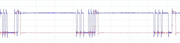
The first image shows me you did not use the input WS as LE for the TDA 1541 A. You must disconnect the LE out from Ians board , not use it at all.Koldby, tried your suggestion of bypassing Ian's board for WS - no difference to the distortion.
Next connected the board to a cheap USB to I2S interface.
Screen shots attached. Still looks like one of the clock cycles is after the rising edge of LE but no distortion heard from Youtube so far. (48Khz)
Does this mean that the I2S data from the Denon Cd player is not actually I2S?
Images: Bck + L, D + BCK, D + L
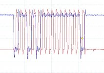
Did you remember to invert the CLK out of Ians board? That is mandatory. The WS(LE) bypass I described, is only to get all 16 bits converted in the TDA1541A. Try to have look on my Pic of CLK and LE ... LE (or WS as it is called as output from the I2S source)should be a 50% dutycycle 44,1 Khz (or 48) squarewave. The aboth 4 CLK pulse long LE is how the faulty LE looks out of Ians board. Don't use that..
You must have the same problem, as everyone else has when using Ians i2stopcm board: The TDA1541a only converts 15 bits.Hi Everyone,
I've been using Ian's boards (SPDIF+FIFO+I2stopcm) with a Red Baron5 TDA1541A (in offset binary mode) and watching this thread with high interest. I'm not a dac guru so the theoretical parts are interesting for me but I'm far from interrupting the discussion. I've never heard that kind of distortion which has been described here. So i would like to get know whether I could catch that distortion in my system or not.
When I assembled my dac, I heard a Madonna Hard candy titled disc (I'm an old fashioned guy listen to CD discs via Micromega Duo spinner) and its last song, the Voices was very distorted and I thought that was something wrong. I have an oscilloscope and I checked the analog signal - and that reached the upper and lower limits. I also checked the analog signal with a stock dvd player and the signal was also from the bottom and to the top - so I realized that this song is deliberately recorded this way. I think I should have found that kind of distortion described in this topic - but I have not seen anything like that on the screen of my scope.
Guys please help me, how to find this distortion? Maybe a popular recent production song title would help, which i could buy in a store physically.
The distortion, on the other hand, batteryman describes, IMHO, is unique for his setup, as neither you, I or ryanj has experienced that and I haven't seen it described anywhere else using this i2stopcm board with TDA1541A.
The first image shows me you did not use the input WS as LE for the TDA 1541 A. You must disconnect the LE out from Ians board , not use it at all.
Did you remember to invert the CLK out of Ians board? That is mandatory. The WS(LE) bypass I described, is only to get all 16 bits converted in the TDA1541A. Try to have look on my Pic of CLK and LE ... LE (or WS as it is called as output from the I2S source)should be a 50% dutycycle 44,1 Khz (or 48) squarewave. The aboth 4 CLK pulse long LE is how the faulty LE looks out of Ians board. Don't use that..
I did use WS for LE, but I did not disconnect it from Ian's board.
Unfortunately, I have blown his board by connecting it to 15v during relocation so I have decided to go down EC Design's discrete route instead, with I2S attenuation as well.
Soldering smd parts will be a challenge with my shaking hands and eyesight
(old age) though I may attempt my own version with through hole components, I need inverted data as well. I really could also do with two I2S inputs so I can switch between CD & USB with a 74157 multiplexer.
- Home
- Source & Line
- Digital Line Level
- Building the ultimate NOS DAC using TDA1541A