Hi koldby,
Simply invert DOL-, DOL+, DOR- and DOR+ outputs of the existing decoder.
This will result in a very small DC-offset in the uV range (typically +1 LSB when the double zero code is fixed) between inverted and none inverted balanced outputs.
Hi John
Thanks for clarifying that. Could you comment on my thoughts on using 4 TDA1541 in a balanced Sign Magnitude DAC. Is it ok to just use inverters on all the 4 datalines (DOL+, DOL- DOR+ DOR-) or should I use the approach with inverting the sampled MSB and build a copy of the AND- OR complex U14 , U15 and U16 ?
Simply invert DOL-, DOL+, DOR- and DOR+ outputs of the existing decoder.
This will result in a very small DC-offset in the uV range (typically +1 LSB when the double zero code is fixed) between inverted and none inverted balanced outputs.
Hi koldby,
Simply invert DOL-, DOL+, DOR- and DOR+ outputs of the existing decoder.
This will result in a very small DC-offset in the uV range (typically +1 LSB when the double zero code is fixed) between inverted and none inverted balanced outputs.
Oh yes that is right, Thanks.
It is not a LSB error, only a DC error...
Oh yes that is right, Thanks.
It is not a LSB error, only a DC error...
It's an LSB error. The idea for a differential output is to cancel any even harmonics and for that the amplitude needs to be precisely matched in terms of the magnitude to work as expected and to cancel out at low leveled signals.
This won't be much of an issue obviously, but lets not treat it as just "DC error" because it's not.
That is actually not my reason for using a balanced system. It is for better noise immunity but that's another story.
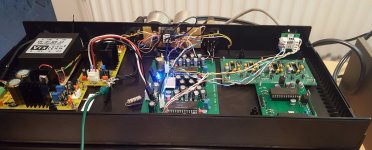
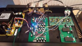
My dual balanced 1541a dac - worked 1st time
At last I received my dual balanced TD1541 pcbs from Pcbway.
I borrowed EC Designs low frequency dem idea and it is running at 89Hz.
Dem caps are Nichicon UKL very low leakage type and there was no waiting for them to charge up.
Power pin decoupling is with Os Con low esr 100uf/16v & 0.1uf Wima.
Dexa low noise regulators are used on the pcb, with adjustable LM317/337 preregulators ($10 each built from Ebay).
The Sowter I/V transformers had to stick out from the rear of the plastic 1U case and the primaries are wired in parallel (across 110R resitors), the secondaries are in series. Then through a 10K alps pot to a Quad 405.
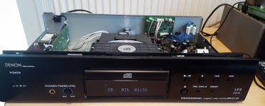
Cat5E STP cable connects it to a Denon professional CD player used as an excellent rack mounting transport in which resides IanCanada's I2StoPcm interface.
I was very pleased when it worked first time and sounds promising though not right as it crackles on peaks.
I've yet to examine the signals with my scope and will fit a shorter Cat5e cable as recommend by IanC. (currently 50cm, 10cm is adequate.)
The other pcbs are: Quad AD1862 and dual AD1865 for comparison and then one of the three will be for CD, and the other connected to a USB to I2S interface for PC audio.
At last I received my dual balanced TD1541 pcbs from Pcbway.
I borrowed EC Designs low frequency dem idea and it is running at 89Hz.
Dem caps are Nichicon UKL very low leakage type and there was no waiting for them to charge up.
Power pin decoupling is with Os Con low esr 100uf/16v & 0.1uf Wima.
Dexa low noise regulators are used on the pcb, with adjustable LM317/337 preregulators ($10 each built from Ebay).
The Sowter I/V transformers had to stick out from the rear of the plastic 1U case and the primaries are wired in parallel (across 110R resitors), the secondaries are in series. Then through a 10K alps pot to a Quad 405.
Cat5E STP cable connects it to a Denon professional CD player used as an excellent rack mounting transport in which resides IanCanada's I2StoPcm interface.
I was very pleased when it worked first time and sounds promising though not right as it crackles on peaks.
I've yet to examine the signals with my scope and will fit a shorter Cat5e cable as recommend by IanC. (currently 50cm, 10cm is adequate.)
The other pcbs are: Quad AD1862 and dual AD1865 for comparison and then one of the three will be for CD, and the other connected to a USB to I2S interface for PC audio.
Attachments
Post 6585 moved to this thread as requested by batteryman.
Thank you and I will remember the 'proper way' to do it if there is a next time.
Hi batteryman,
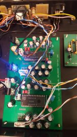
When looking at your setup, it's a miracle that it actually works at all") .
.
When using relatively long twisted pairs interlinks, one also has to use suitable differential line drivers / receivers and apply correct impedance matching.
I suggest to have a look at RS485/RS422 transceiver chips and related application notes.
When looking at your setup, it's a miracle that it actually works at all
.When using relatively long twisted pairs interlinks, one also has to use suitable differential line drivers / receivers and apply correct impedance matching.
I suggest to have a look at RS485/RS422 transceiver chips and related application notes.
Hi batteryman,
When looking at your setup, it's a miracle that it actually works at all
When using relatively long twisted pairs interlinks, one also has to use suitable differential line drivers / receivers and apply correct impedance matching.
I suggest to have a look at RS485/RS422 transceiver chips and related application notes.
It was a surprise it worked to me too as its very much in the experimental stage.
Once I have pinpointed what sounds like digital clipping - distortion on peaks which worsens with amplitude, not on quiet passages I plan on using a digital isolator, possibly a Max2244. The cable is being replaced with a 15cm one.
I am wondering whether the I2S data being received by the I2S-pcm interface is not 16bit as the cd player uses as PCM1901a which is a 24bit dac? IanC has suggested trying half speed mode.
The pcm signals show ringing but are otherwise not distorted but I need to investigate the grounding.
Dear EC AND batteryman
Both of you seems have some experience of transformer output
May I know the suggestion of the section?brand? Type? Value?
Is it better then op or passiveIV?
My transformers are from Sowter type 9545 which has now been superceded by: 1465 DAC Interface Transformer
They are expensive, but do an excellent job of filtering a NOS dac, especially a balanced setup and depending on how you connect it, offer a step-up ratio of x5 or x10.
I've used the transformers with a dual 1541, and an Audio Note Dac1.1 (AD1865) kit with no other filtering.
Screenshot
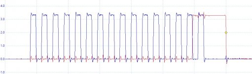
Here's a screen shot of the latch and bck, which look okay to me and of course you can see the clock stop feature of Ian's interface.
I will try half speed mode next and if that doesn't help, I'll move the interface into a Marantz Cd65 1541 based cd player.
Here's a screen shot of the latch and bck, which look okay to me and of course you can see the clock stop feature of Ian's interface.
I will try half speed mode next and if that doesn't help, I'll move the interface into a Marantz Cd65 1541 based cd player.
Attachments
Hi batteryman,
LE latches the TDA1541A outputs (simultaneous mode) at the -rising- edge of LE (datasheet spec).
When the red trace represents LE and it runs synchronous with BCK (no scope trigger issue), it latches the outputs -before- all 16 bits have been clocked in.
So if I am correct, all you have to do is invert LE. Perhaps Ian already made a provision for this (jumper setting?).
Here's a screen shot of the latch and bck, which look okay to me and of course you can see the clock stop feature of Ian's interface.
I will try half speed mode next and if that doesn't help, I'll move the interface into a Marantz Cd65 1541 based cd player.
LE latches the TDA1541A outputs (simultaneous mode) at the -rising- edge of LE (datasheet spec).
When the red trace represents LE and it runs synchronous with BCK (no scope trigger issue), it latches the outputs -before- all 16 bits have been clocked in.
So if I am correct, all you have to do is invert LE. Perhaps Ian already made a provision for this (jumper setting?).
So if I am correct, all you have to do is invert LE. Perhaps Ian already made a provision for this (jumper setting?).
I'm afraid that won't work.
I've noticed that TDA1540/TDA1541A uses falling edge of LE to clean up input register.
In short - LE cannot change during clocking-in data. That is in both ways (whether it's falling or rising).
On a side note, here is what you can achieve with TDA1540 and a proper digital filter with a dithering:
An externally hosted image should be here but it was not working when we last tested it.
That's a -96 dBFS signal which in normal conditions is on 18th bit. In general you cannot play anything below -72 dBFS on 14 bit converter since it looks like this:
An externally hosted image should be here but it was not working when we last tested it.
That is just switching noise of the MSB. Nothing else (it looks exactly the same from -73 dBFS to -100 dBFS).
Proper manipulation with dithering can in fact increase the resolution of the DAC itself.
Last edited:
Hi
I’m not sure if someone read this from me already
Thus I think it might be a general problem for the digital expert here
philips cd104 tda1540 NOS modify error... - diyAudio
I’m not sure if someone read this from me already
Thus I think it might be a general problem for the digital expert here
philips cd104 tda1540 NOS modify error... - diyAudio
Hi batteryman,
LE latches the TDA1541A outputs (simultaneous mode) at the -rising- edge of LE (datasheet spec).
When the red trace represents LE and it runs synchronous with BCK (no scope trigger issue), it latches the outputs -before- all 16 bits have been clocked in.
So if I am correct, all you have to do is invert LE. Perhaps Ian already made a provision for this (jumper setting?).
I am now confused! According to Ian's instructions, the data appears at the output on the negative transition of WE which is what my screen shot shows. But according to the data sheet, this only applies to time multiplexed TWC.
"The converted samples appear at the output, at the first positive going transition of the bit clock signal after a negative going transition of the word select signal."
You are correct in saying that in simultaneous mode, that its the positive going transition as the datasheet states:
"The converted samples appear at the output at the positive going transition of the latch enable signal."
So this might explain why the data is truncated and causing the distortion.
I will re examine the traces when I have replaced the 50cm cat5e cable with a 15cm Cat6 cable tomorrow, and in the meantime I can try Ian's suggestion of half speed mode.
Many thanks for your comments.
Hi
I’m not sure if someone read this from me already
Thus I think it might be a general problem for the digital expert here
philips cd104 tda1540 NOS modify error... - diyAudio
It looked like a psu issue to me. How hot are the regulators getting?
When they get hot, you get the problem, hence try the freezer spray as suggested, but on the regulators.
So this might explain why the data is truncated and causing the distortion.
I will re examine the traces when I have replaced the 50cm cat5e cable with a 15cm Cat6 cable tomorrow, and in the meantime I can try Ian's suggestion of half speed mode.
Many thanks for your comments.
I don't think so. TDA1541A can operate at 14 bits just like TDA1540 and it does work just fine. You wouldn't hear any difference between 14 bits and 16 bits.
I can imagine there is another issue. Can you show us the DATA line (whether it's R or L, doesn't matter) along with BCLK on the same screen? If you can include 3rd graph of LE that would be lovely, but that's not necessary.
Hi batteryman,
Philips TDA1541A datasheet page 4
quote:
When input OB/TWC input is connected to VDD1 the two channels of data (L/R) are input simultaneously via DATA L and DATA R, accompanied with BCK and a latch-enable input (LE). With this mode selected the data must be in offset binary. The converted samples appear at the output at the positive going transition of the latch enable signal.
The format of the data input signals is shown in Fig.5 and 6.
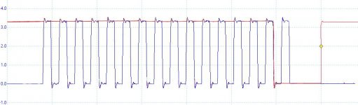
When you invert LE, the positive going transition (latching) will occur -after- all bits have been clocked in. This would meet datasheet specs and should work.
See attached modified oscillogram.
I am now confused! According to Ian's instructions, the data appears at the output on the negative transition of WE which is what my screen shot shows. But according to the data sheet, this only applies to time multiplexed TWC.
Philips TDA1541A datasheet page 4
quote:
When input OB/TWC input is connected to VDD1 the two channels of data (L/R) are input simultaneously via DATA L and DATA R, accompanied with BCK and a latch-enable input (LE). With this mode selected the data must be in offset binary. The converted samples appear at the output at the positive going transition of the latch enable signal.
The format of the data input signals is shown in Fig.5 and 6.
When you invert LE, the positive going transition (latching) will occur -after- all bits have been clocked in. This would meet datasheet specs and should work.
See attached modified oscillogram.
Attachments
- Home
- Source & Line
- Digital Line Level
- Building the ultimate NOS DAC using TDA1541A