Thanks for your suggestions. I will try the STOPPERS but excuse my ignorance I am afraid it will change the value of the I/V res if not big value /in parallel/ ??
Regards,
Ignat
Now I can't calculate: but the influence is beyond the few hundred kHz. There is "nothing" parallel to the I/V. So there is no influence in the "passband", which is audio.
Hello, triode_al.
I'm planning to compare a Lampizator SRPP-output stage, a D3a output stage and a Kondo-inspired output stage with 6072 tubes. I see that you have something you call a "Kondo post-I/V filter". What is that, and can you please share your experiences regarding tube based output stages for the 1541A?
Kind regards,
Vidar
Now I can't calculate: but the influence is beyond the few hundred kHz. There is "nothing" parallel to the I/V. So there is no influence in the "passband", which is audio.
Something is wrong /could be my understanding/ - the I/V resistor stays there and the voltage goes straight to the grid of the triode -if he stopper is from the grid to the ground it is in parallel ?? or I am mistaken.
Thanks
Hello, triode_al.
I'm planning to compare a Lampizator SRPP-output stage, a D3a output stage and a Kondo-inspired output stage with 6072 tubes. I see that you have something you call a "Kondo post-I/V filter". What is that, and can you please share your experiences regarding tube based output stages for the 1541A?
Kind regards,
Vidar
Hi,
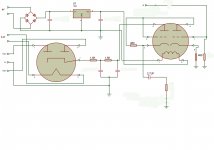
Just for your reference - my very simple tube buffer /in my case with Bendix 6385/ - just a principle schematics - to be revised.
Regards,
Ignat
Attachments
Last edited:
Hi ceglar
But we could also use passive amplification plus RF filtering based on a step up transformer. Transformer with 1:10 transformation ratio would give us around 4Vpp. Output voltage can be lower in practical circuits due to losses.
Enjoy.
what transformer would you advice for best sound ?
I need a transformer with double secondary to drive directly the power mosfets of a pass F6 amp... could it be feasible?
no need of a fet buffer there? as the impedance of the lateral mosfets is quite high?
Hello, triode_al.
I'm planning to compare a Lampizator SRPP-output stage, a D3a output stage and a Kondo-inspired output stage with 6072 tubes. I see that you have something you call a "Kondo post-I/V filter". What is that, and can you please share your experiences regarding tube based output stages for the 1541A?
Kind regards,
Vidar
I attach a design record.
The first stage is called a Kondo stage. The whole filter amplifies: none. Bandpass : around 21 kHz.

albert
Note: This filter derives from the standard Philips concept of the TDA1541 players. It is such that it maximally compensates for the SAA7220/TDA1541 combination that already has a small uplift around 20 kHz to compensate
Something is wrong /could be my understanding/ - the I/V resistor stays there and the voltage goes straight to the grid of the triode -if he stopper is from the grid to the ground it is in parallel ?? or I am mistaken.
Thanks
My problem of writing took much words.
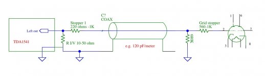
here is my idea:
View attachment 453163
The Stopper1 prevents extreme HF noise to be propagated in the connected line. I have depicted a coax, which also serves such a purpose. And the drawing suggests not using the shield as interconnect for the earth.
albert
Attachments
The Stopper1 prevents extreme HF noise to be propagated in the connected line. I have depicted a coax, which also serves such a purpose. And the drawing suggests not using the shield as interconnect for the earth.
albert
Noted, thanks.
My problem of writing took much words.
here is my idea:
View attachment 453163
The Stopper1 prevents extreme HF noise to be propagated in the connected line. I have depicted a coax, which also serves such a purpose. And the drawing suggests not using the shield as interconnect for the earth.
albert
Invalid Attachment specified. If you followed a valid link, please notify the administrator

I attach a design record.
The first stage is called a Kondo stage. The whole filter amplifies: none. Bandpass : around 21 kHz.
Thank you triode_al for the explanation.
Hi marconi118
I suggest to test a cheap 1.5VA transformer first, I used this one:
TEZ1.5/D230/15-15V BREVE TUFVASSONS - Transformer: encapsulated | TME - Electronic components
Breve-Tufvassons TEZ1.5/D/15-15V, 230V ac, 2 x 15V secondary, 1.5VA.
If you like the result you may have a look at Sowther, Lundahl or even Hashimoto for a higher quality audio transformer.
If you are planning to drive the F6 directly from the TDA1541A you will need high gain (100 and up). Then output impedance would be too high, causing severe trebles and midrange roll-off.
I suggest to use multiple transformer amplification stages with buffers in between. These could even be combined with a TVC for volume control.
what transformer would you advice for best sound ?
I suggest to test a cheap 1.5VA transformer first, I used this one:
TEZ1.5/D230/15-15V BREVE TUFVASSONS - Transformer: encapsulated | TME - Electronic components
Breve-Tufvassons TEZ1.5/D/15-15V, 230V ac, 2 x 15V secondary, 1.5VA.
If you like the result you may have a look at Sowther, Lundahl or even Hashimoto for a higher quality audio transformer.
I need a transformer with double secondary to drive directly the power mosfets of a pass F6 amp... could it be feasible?
If you are planning to drive the F6 directly from the TDA1541A you will need high gain (100 and up). Then output impedance would be too high, causing severe trebles and midrange roll-off.
I suggest to use multiple transformer amplification stages with buffers in between. These could even be combined with a TVC for volume control.

Invalid Attachment specified. If you followed a valid link, please notify the administrator
For some reason the picture showed up in the wrong place but the drawing in the bottom is the one intended.
Don't send the administrators chasin' me
Last edited:
.......RF filtering based on a step up transformer......
Thanks for sharing your step up transformer output design.
Please can I ask some basic questions?
What kind of RF comes out of the TDA1541a?
Can a step up transformer be wound to also band limit as a low-pass analogue filter?
Do you think a low-pass analogue filter is needed for a NOS TDA1541a DAC?
Your expert opinions are very much appreciated.
I used a cheap 1.5VA safety transformer with air gap (230V primary, 2 x 15V secondary) for testing. Transformation ratio equals 230 / 15 = 15.33.
Enjoy.
Hi John,
Thanks for sharing your bright ideas /as usual/. I suppose the trafo should be placed as close to the dac chip as possible ??
Regards,
After a long time of not posting I've gone back to playing with the tda1541a. I have an old +-14v 400ma (it measures slightly different loaded) Audio Alchemy PSU that I dismantled the output cable and ran in to an old tda1541a NOS kit I had. I then take the current tda1541a output to a breadboard I/V. The kit did have a separate IV board based on FET's but I couldn't bias the thing to the correct level on the +-14v PSU probably as I need +-2v's headroom...
My current breadboard I/V output stage is one opa627 per channel with approximately 4700pf poly-prop' cap and 2K resistor in the feedback loop and a 2.2uf poly-prop dc blocker cap. I have yet to add a filter / buffer. Sounds decent but I've not gone through the maths to calculate the expected HF noise. As I am on breadboard there is always the option of knocking something together.
How does one correctly distribute the current out of the tda1541a? After discovering a damaged track or solder joint I noticed that picking up for the breadboard input tda1541a current out from various places- one of either the tda1541a output pin directly, along a 5cm track, and a terminal block at the end of 5cm track changed the sound both in quality and volume levels (including measured current out). The worst was the terminal block at the 5cm track end and suspect that might be a combination of issues one being the electrical termination issue at the block.
Last edited:
Hi kazap,
- Quantization noise (difference between original analogue signal and approximated, step-shaped zero order hold TDA1541A output signal).
- I2S switching noise (switching noise that enters the I2S interface pins and switching noise generated by on-chip circuits processing I2S).
- DEM switching noise (Switching noise generated by DEM oscillator, shift register, and DEM switch matrix).
- Power supply noise (power supply noise / ripple and load induced noise).
As transformation ratio goes up, output impedance will increase with a given input impedance. The presense of stray capacitance can form a low-pass filter.
Low-pass corner frequency can be tuned by changing the transformation ratio and or capacitive loading.
Based on my practical experience I would advise not to place a low pass filter after a NOS DAC.
What kind of RF comes out of the TDA1541a?
- Quantization noise (difference between original analogue signal and approximated, step-shaped zero order hold TDA1541A output signal).
- I2S switching noise (switching noise that enters the I2S interface pins and switching noise generated by on-chip circuits processing I2S).
- DEM switching noise (Switching noise generated by DEM oscillator, shift register, and DEM switch matrix).
- Power supply noise (power supply noise / ripple and load induced noise).
Can a step up transformer be wound to also band limit as a low-pass analogue filter?
As transformation ratio goes up, output impedance will increase with a given input impedance. The presense of stray capacitance can form a low-pass filter.
Low-pass corner frequency can be tuned by changing the transformation ratio and or capacitive loading.
Do you think a low-pass analogue filter is needed for a NOS TDA1541a DAC?
Based on my practical experience I would advise not to place a low pass filter after a NOS DAC.
Really? A 15khz sine wave looks bad without a filter on a nos dac. With LC filters you can get 20khz looking(not perfect, but) reasonably good. Imo you should use a filter because it results in more natural sound. I used many nos dac without filter and dont like it. My 2c. But each to their own. No offence to anyone.

- Home
- Source & Line
- Digital Line Level
- Building the ultimate NOS DAC using TDA1541A