Hi EC,
That is interesting! Will the autodetecting module be an all SMD preassembled module or can we have a BOM for a PCB only option?
I'm about to order my parts for the DI16core
I'm glad to hear that. If you like the passive way you ought to try TVC's: you could avoid the summing opamp on your personal setup and go balanced (as I will probably do) . Then you can chose unbalanced or balanced output, depending on your amps
There is one pair of Stevens & Billington's transformers rigth now at the Market Place...shamelly I'm short of funds
Regards,
M
I have been working on both DI 8 (48/64 BCK) auto-detecting timing module and the universal I2S interface.
That is interesting! Will the autodetecting module be an all SMD preassembled module or can we have a BOM for a PCB only option?
I'm about to order my parts for the DI16core
Using the LM4562 enhances details significantly, sound is much clearer, and it doesn't sound laid-back at all like the OPA627.I also completely removed the (active) control amplifier. this increased sound quality significantly, the passive one (stepped resistor volume control) produces a much cleaner sound.
I'm glad to hear that. If you like the passive way you ought to try TVC's: you could avoid the summing opamp on your personal setup and go balanced (as I will probably do) . Then you can chose unbalanced or balanced output, depending on your amps
There is one pair of Stevens & Billington's transformers rigth now at the Market Place...shamelly I'm short of funds
Regards,
M
Re: OP-amps for I/V stage
I suggest John build a good pre-amp with tubes or discrete with fets, with your knowledge no problem
A good preamp enhances the dynamic responce and low level detail. A good output in dac sounds good too, but slightly less dynamic imo.
I lately compared the sound from my SRPP 6SN7 preamp directly, as source modded cdp, could switch and so compare directly. Listened with tubed headphone amp and AKG headphone. I could allmost hear no difference, only a slightly less dynamic sound without preamp. (made this switch on preamp to possibly boost a source some extra to headphone amp)
One of the best sound enhancing gear i did build was the pre-amp. Rest must be relatively good too ofcourse.
I will ask a friend of my, he knows someone in the electronic buisiness that who might order some of the LM4562 in soic and dil.
-ecdesigns- said:I also completely removed the (active) control amplifier. this increased sound quality significantly, the passive one (stepped resistor volume control) produces a much cleaner sound.
So now I basically drive the MOSFET power amplifier directly with the DI DAC, this is no problem as the DI DAC output amplitude can be adjusted by modifying the output attenuator. It will provide enough signal amplitude to drive virtually any power amplifier directly.[/B]
I suggest John build a good pre-amp with tubes or discrete with fets, with your knowledge no problem
A good preamp enhances the dynamic responce and low level detail. A good output in dac sounds good too, but slightly less dynamic imo.
I lately compared the sound from my SRPP 6SN7 preamp directly, as source modded cdp, could switch and so compare directly. Listened with tubed headphone amp and AKG headphone. I could allmost hear no difference, only a slightly less dynamic sound without preamp. (made this switch on preamp to possibly boost a source some extra to headphone amp)
One of the best sound enhancing gear i did build was the pre-amp. Rest must be relatively good too ofcourse.
> I can only suggest to give the LM4562 a try.[/B]
I will ask a friend of my, he knows someone in the electronic buisiness that who might order some of the LM4562 in soic and dil.
Final DI 8 PCBs tested
Hi all,
Project update,
Yesterday I finally received the DI8 power supply and DI8 timing module PCBs. So I couldn't wait and assembled them for testing. Both work fine.
This means that all 10 different DI DAC PCBs function, and all components fit. Not bad regarding that some of them were redesigned / optimized without testing a prototype PCB.
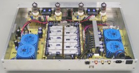
I added a photograph of the current DI 8M prototype. All prototype PCBs have been replaced with the professional ones now.
The large PCB on the right is the DI8 power supply, the timing module is located in the center at the bottom of the photograph. The large heat sink is temporarily removed.
The small PCB close to the RCA sockets is the output attenuator, I haven't made a professional PCB for this one yet, as it's a simple single-sided PCB. The yellow multilayer capacitors are used to couple ac signals to chassis. The audio signals are routed trough a aluminum cable duct to minimize interference. The third RCA plug (next to the mains connection) is used for remote power ON/OFF. The RCA sockets for L + R channles could be replaced by higher quality types, but this requires modifying the rear panel.
All voltage regulators of both DA1541A and IVDIF modules are now matched to 10mV. I used a test setup with a socket for the voltage regulator to be tested, I also connected a 1 KOhm load. Next I Tested 100pcs of each type, and wrote the measured voltage on the back. Finally I picked out those regulators that matched most closely. The DI8 main board assembly is different from the original schematics now. I changed the DEM clock circuit in order to lower phase noise. I now use a resistive divider. The ring core transformer is no longer necessary. The removed parts are replaced by wire bridges.
The I/V resistors for the OP-amp I/V stage were replaced by a resistor combined of 8 4.7 KOhm low noise / low inductance SMD resistors in parallel. I was also able to use LM4562 TO-99 for both I/V stage and diff amp, because the IVDIF modules are now modified to accept a DUAL OP-amp, as the prototype was designed for the single OPA627 in the diff amp. So I had to use a adapter socket and a LM4562 SO8 version then.
I used a low jitter custom oscillator module on the USB/DI2S module (next to the DI8 power supply). It's the small black PCB with the crystal on top. Another improvement on the USB/DI2S module was replacing the 74F163 with a 74HC(T)161, this lowers the crystal oscillator load. The binary counter is used to provide a 12MHz clock for the PCM2706, it's not critical.
I used silvered mica bypass capacitors for the Intertechnik coupling caps in the TUBEDIF modules. The ECC83S was replaced by a ECC83S balanced version (factory selected for low noise, best sound quality and matched triode specifications). This enhances the operation of the differential tube input stage. I switched back to the ECC82 for the cathode follower, because it has a lower output impedance, and the allowed voltage between filament and cathode is higher (cathode is at 90V potential).
I also made RCA interlinks, using stranded (litze) wire, similar to the sonic resonator interlinks. These have very low inductance and low capacitance (only approx. 10pF at 60cm). By significantly reducing the capacitive load, phase shifts (using a passive resistive volume control) are minimized. The audio interlinks inside the DI 8M carry high amplitude signals, driven by a low impedance, so they are less critical.
Hi all,
Project update,
Yesterday I finally received the DI8 power supply and DI8 timing module PCBs. So I couldn't wait and assembled them for testing. Both work fine.
This means that all 10 different DI DAC PCBs function, and all components fit. Not bad regarding that some of them were redesigned / optimized without testing a prototype PCB.
I added a photograph of the current DI 8M prototype. All prototype PCBs have been replaced with the professional ones now.
The large PCB on the right is the DI8 power supply, the timing module is located in the center at the bottom of the photograph. The large heat sink is temporarily removed.
The small PCB close to the RCA sockets is the output attenuator, I haven't made a professional PCB for this one yet, as it's a simple single-sided PCB. The yellow multilayer capacitors are used to couple ac signals to chassis. The audio signals are routed trough a aluminum cable duct to minimize interference. The third RCA plug (next to the mains connection) is used for remote power ON/OFF. The RCA sockets for L + R channles could be replaced by higher quality types, but this requires modifying the rear panel.
All voltage regulators of both DA1541A and IVDIF modules are now matched to 10mV. I used a test setup with a socket for the voltage regulator to be tested, I also connected a 1 KOhm load. Next I Tested 100pcs of each type, and wrote the measured voltage on the back. Finally I picked out those regulators that matched most closely. The DI8 main board assembly is different from the original schematics now. I changed the DEM clock circuit in order to lower phase noise. I now use a resistive divider. The ring core transformer is no longer necessary. The removed parts are replaced by wire bridges.
The I/V resistors for the OP-amp I/V stage were replaced by a resistor combined of 8 4.7 KOhm low noise / low inductance SMD resistors in parallel. I was also able to use LM4562 TO-99 for both I/V stage and diff amp, because the IVDIF modules are now modified to accept a DUAL OP-amp, as the prototype was designed for the single OPA627 in the diff amp. So I had to use a adapter socket and a LM4562 SO8 version then.
I used a low jitter custom oscillator module on the USB/DI2S module (next to the DI8 power supply). It's the small black PCB with the crystal on top. Another improvement on the USB/DI2S module was replacing the 74F163 with a 74HC(T)161, this lowers the crystal oscillator load. The binary counter is used to provide a 12MHz clock for the PCM2706, it's not critical.
I used silvered mica bypass capacitors for the Intertechnik coupling caps in the TUBEDIF modules. The ECC83S was replaced by a ECC83S balanced version (factory selected for low noise, best sound quality and matched triode specifications). This enhances the operation of the differential tube input stage. I switched back to the ECC82 for the cathode follower, because it has a lower output impedance, and the allowed voltage between filament and cathode is higher (cathode is at 90V potential).
I also made RCA interlinks, using stranded (litze) wire, similar to the sonic resonator interlinks. These have very low inductance and low capacitance (only approx. 10pF at 60cm). By significantly reducing the capacitive load, phase shifts (using a passive resistive volume control) are minimized. The audio interlinks inside the DI 8M carry high amplitude signals, driven by a low impedance, so they are less critical.
Attachments
Passive volume control / DI DACs
Hi MGH,
Thanks for your reply [post #1380]
Sorry for the late reply,
> Well the passive stepped volume control is a actually a separate unit, and yes it has a remote control.
It has 64 steps and uses both reed relays, and very low noise / low inductance SMD resistors to keep the signal path as short as possible. It also has two separate relay groups for left and right channels, this ensures optimal channel separation.
To indicate the volume setting, a multi-color RGB LED is used, volume settings are indicated with blue (low), green (medium) and red (high). Intermediate steps use mixed colors from either blue-green or green-red. It has a variable muting level.
The reed relays are driven using sequential switching patterns and delays, in order to minimize pops and clicks during volume adjustment.
> By adding more (pre) amplifiers to the signal path (tri-amping and active crossovers), you probably add more distortion. However It's possible to get multiple outputs from the DI DACs by changing the output attenuator circuit.
Hi maxlorenz,
Thanks for your reply [post #1381]
Since the auto-detecting PCBs need to be relatively small, I have to use SMD components. Still I need some programmable logic chips (PAL), in order to reduce the amount of components needed. I plan to use trough hole chips for these. If you feel confident soldering SMD parts, you can use the PCB only option.
The ICs for the DI 16(M) timing-chain are placed in IC sockets, so it's easy to remove the chips and place the dual format module on the existing IC sockets later. Since the DI 8(M) is modular, the timing-chain module can be easily swapped for a auto-detecting module.
The dual format timing module only selects the correct taps according to the number of BCK pulses during WS. It basically consists of a detector (48/64BCK), two timing-chains and a multiplexer that selects the correct taps on both timing-chains according to the detector output. In some cases, additional glue logic needs to be added, like when using the Sony format.
> About TVCs, are you referring to the Stevens & Billington's TX-120 mkII copper TVC?
In general, I have some issues with TVCs, first the long signal paths and crosstalk. Next DC should be completely avoided, so a coupling capacitor seems to be necessary, just in case. Signal amplitude at lower frequencies should be kept low, in order to avoid distortion. The transformer should be well shielded, so basically a mu-metal housing is necessary.
When connecting it to both DI DAC I/V stages, the 16...22Vpp combined signal amplitude should be lowered first (attenuator), this could cause problems with output impedance. The mixed mode option would no longer be possible in it's current form.
I looked-up some TVC specifications on the internet. Bandwidth is approx. 60...100KHz, THD approx. 0.03% and phase shift at 20 KHz approx. 1 degree. The attenuation steps are also rather course (20...24 steps).
great project
Looks like a terrific project - my compliments on the terrific work.
I would love to try assemble a DIY kit, but looking at the web site the PCBs alone cost between 150-450 euro's depending on the model - that's without housing or components.
I understand you've put a lot of work into the project - so congratulations on a job well done.
Before dishing out $200 on the DI-16 PCB's - I'd love to see some comparisons to say - a modded Zhalou with the LM4562's & blackgates to understand how much audio quality is different.
For me it's a lot of work and extra money to buy the $200 PCB and source the components locally then build the kit - vs just buying the Zhalou.
Has anyone had a chance to listen to both side by side?
..David
Hi EC,
Do you mean that you will manage to build the auto-detecting PCB pin-to-pin compatible with the existing timing chain, as a drop-in repl. That would be very useful.
And for that I could use some help
Well, how goes the saying? you have to eat the cake to know how is the taste...or something like that
About steps, it sounds so good that I use only one position
Hi David,
I think John's perfectionism is to blame. I would say that his kits are not the usual DIY kit because they are ment to be definitive to some extent (not tweakable). A priori only the power supply seems upgradable. All the other components are high quality and high cost. For example, the sockets are high quality and cost many times the price of the chips they will support...the PCB option is IMHO the way to go
Best,
M
Since the auto-detecting PCBs need to be relatively small, I have to use SMD components. Still I need some programmable logic chips (PAL), in order to reduce the amount of components needed. I plan to use trough hole chips for these. If you feel confident soldering SMD parts, you can use the PCB only option.
Do you mean that you will manage to build the auto-detecting PCB pin-to-pin compatible with the existing timing chain, as a drop-in repl. That would be very useful.
Yes> About TVCs, are you referring to the Stevens & Billington's TX-120 mkII copper TVC?
When connecting it to both DI DAC I/V stages, the 16...22Vpp combined signal amplitude should be lowered first (attenuator), this could cause problems with output impedance.
And for that I could use some help
I looked-up some TVC specifications on the internet. Bandwidth is approx. 60...100KHz, THD approx. 0.03% and phase shift at 20 KHz approx. 1 degree. The attenuation steps are also rather course (20...24 steps).
Well, how goes the saying? you have to eat the cake to know how is the taste...or something like that
About steps, it sounds so good that I use only one position
Hi David,
I think John's perfectionism is to blame. I would say that his kits are not the usual DIY kit because they are ment to be definitive to some extent (not tweakable). A priori only the power supply seems upgradable. All the other components are high quality and high cost. For example, the sockets are high quality and cost many times the price of the chips they will support...the PCB option is IMHO the way to go
Best,
M
DIY XO
Hi John
I managed to get the interior of an opened Xtal working with its chip, as you suggested.
But i have a small problem with my diy XO: The waveform is not symmetric, the upper half has less surface then the lower. Is this a problem? I don't think so when everything is depending (in dac) on 1 (rising) edge, but on this way the falling edge is not exact in the middle of wave.
But what i can see at cristal itself compared to buffered diyXO output: the XO is a lot faster (steeper squarewave with some overshoot) and has less jitter (finer curve)
The internal chip is a TI031X, i think it's a sort of comparator. Pin 5 is out, 4 Gnd and 8 Vcc as usual. Output is not high, on 5.1V PS only 1.6V out, mostly it's about 50% duty and so 2.5V as Tents XO's usually shows.
The cristal is fed to pin 2/3 and 5/6 with a current divider of 2 resistors. Took a standard cristal. (27Mhz for the DVD player, i don't re-use the SMD cristal)
The waveform could get more symmetric when i change those resistors, but they are under the chip on a ceramic XO pcb, and so not easy to change. I glued the ceramic on a perfboard where the cristal rests on.
For PS i made on perfboard a cheap version of "the flea" (with a NE5534 instead of AD797) has a gyrator, nice silent ps. I now listen to the flea with a 11Mhz Tent XO, sounds great, a good design. (PCM56 non-os, with I2S glue logic from a SAA7210)
Thanks for reply.
Hi dear,
A question, while we wait...
The individual heatsinks for the 1543 DAC chips are difficult to get for me. I can put a big Al plate to make a common heatsink for the 16 dacs, as your did for the D8.
Must this common heatsink plate be grounded?
I guess yes...
Cheers,
M
A question, while we wait...
The individual heatsinks for the 1543 DAC chips are difficult to get for me. I can put a big Al plate to make a common heatsink for the 16 dacs, as your did for the D8.
Must this common heatsink plate be grounded?
I guess yes...
Cheers,
M
Hi maxlorenz,
Thanks for your reply [post #1388]
sorry for the very late reply, busy as usual...
> Yes, I plan to design the DI16 auto detecting timing module, so it can be directly placed in the existing DI16 timing chain IC sockets.
> The I/V converter output amplitude can easily be attenuated by using resistor attenuators, similar to the one used on the diff amp output.
> I have very good results with the resistive passive attenuator, impedance matching and short low-capacitance interlinks are most important.
> I have been developing / constructing simple air coils for the sonic resonator passive crossover filter. Coils are extremely critical for high-end sound applications, so I try to avoid coils / transformers whenever possible.
DAC chips
Hi tubee,
Thanks for your reply [post #1389]
> I suppose that a slight signal asymmetry isn't that problematic. Low jitter is more important.
> I compared a master clock running on a battery vs running on a plain power supply, filtered with Murata filters and using correct decoupling. I couldn't hear any difference.
> You say the PCM56/SAA7210 combination sounds great, can you specify that more accurately? what exactly is the subjective difference in sound quality between the TDA1541A and PCM56? Are you completely satisfied with the PCM56 sound, or are there still some "issues" with it?
Comparisons with the TDA1541A are not entirely fair, as the vast majority of applications only use a fraction of the true TDA1541A performance.
NOS DACs have very low resolution, this results in quantisizing errors. These errors result in noise proportional to the signal amplitude. This is going to be audible one way or the other, regardless of the DA converter chip used.
With both low signal amplitudes, and high frequencies, this effect is even worse, and results in almost square wave shaped audio signals.
DI 16 Heatsinks
Hi maxlorenz,
Thanks for your reply [post #1390]
Yes, waiting is the worst.
I used small chipset heatsinks for the TDA1543. You could look for brands like Cooler master, Thermaltake or Zalman.
When ambient temperature isn't too high, the housing is large enough, and the DI DAC isn't switched-on permanently, the TDA1543 chips need no heatsinks.
The DI 16 core is designed in a way that the TDA1543 chips are placed well apart, and are not stacked. This ensures optimal heat dissipation.
Making a single heatsink for the DI 16 is difficult because of tolerances in both component height and bending of the PCB. These tolerances are compensated in the DI 8 by clamping small heatsinks to the TDA1541A chips first, then mounting a large heatsink on top of the smaller ones. The DA1541A module connectors enable component height compensation.
The common heatsink could be grounded, however, the DI DACs are very insensitive to interference due to both the balanced design, and the high signal amplitudes used.
Re: DAC chips
Hi John.
It was a while ago a posted my comments, so had to look back first what i stated.
The diy clock is 27Mhz, ideal for the SACD DVD player. Will fidlle it in sometime, but am not hasty with it, its brandnew and has 2 years guarantee. When it's modded guarantee will stop too i guess.
A clock on a battery is not the best imo, a battery can show more noise then a proper ps from mains. But its isolated from the other circuitry with battery.
I am not completely done with PCM56 experiments, am busy to build a tube stage for it with I/V resistor.
I used the very fast AD844 I/V from Pedja. Very peculiar is when i start it up it sounds good, but after an evening the treble gets attenuated and thus annoying.
But what i can say is till now, PCM56 sounds more transparent compared to the TDA1541, in special when they run non-os. I can discribe it at best like: a TDA1541 sounds like a bipolar transistor, and the PCM56 as a fet. TDA emphasises bass-mid and PCM high-mid, then you know what i'm saying. Female voices sound better with the PCM, male with TDA!
Also the music is faster with the PCM56, maybe has it a faster settling time, never checked it. But that could be due the AD844 too.
The TDA can compress the music very slightly in difficult passages, the PCM never showes that.
But the 1541 has qualities i don't get from a PCM56, for instance some "phase" differences, or stereo, or maybe Q-sound effects, these are very clear with the TDA, and not with the PCM56, that one can sound some "flat"
The TDA sounds to me like a "rough diamond" and you can have a lot of fun with it on an evening (but with OS, i still have the 7220). The PCM56 showed here by me a very wide soundstage, wider then TDA, but TDA1541 with 7220 (and mods) has a deeper soundstage.
The PCM56 in nonos show some of the same typical non-os facts as with the TDA1541(higher distorsion)
And all matter of taste again. As you said, there are still some issues with it.
Even digital OS-sed(4X) the resolution of the 1541 is low, if i compare it with my DVD/SACD sound. But it sounds more "special" with the TDA, or it could be i am listening to the added (2nd) harmonics. I should try a PMD100, capable of 8X
-ecdesigns- said:Hi tubee,
Thanks for your reply [post #1389]
> I suppose that a slight signal asymmetry isn't that problematic. Low jitter is more important.
> I compared a master clock running on a battery vs running on a plain power supply, filtered with Murata filters and using correct decoupling. I couldn't hear any difference.
> You say the PCM56/SAA7210 combination sounds great, can you specify that more accurately? what exactly is the subjective difference in sound quality between the TDA1541A and PCM56? Are you completely satisfied with the PCM56 sound, or are there still some "issues" with it?
Comparisons with the TDA1541A are not entirely fair, as the vast majority of applications only use a fraction of the true TDA1541A performance.
NOS DACs have very low resolution, this results in quantisizing errors. These errors result in noise proportional to the signal amplitude. This is going to be audible one way or the other, regardless of the DA converter chip used.
With both low signal amplitudes, and high frequencies, this effect is even worse, and results in almost square wave shaped audio signals.
Hi John.
It was a while ago a posted my comments, so had to look back first what i stated.
The diy clock is 27Mhz, ideal for the SACD DVD player. Will fidlle it in sometime, but am not hasty with it, its brandnew and has 2 years guarantee. When it's modded guarantee will stop too i guess.
A clock on a battery is not the best imo, a battery can show more noise then a proper ps from mains. But its isolated from the other circuitry with battery.
I am not completely done with PCM56 experiments, am busy to build a tube stage for it with I/V resistor.
I used the very fast AD844 I/V from Pedja. Very peculiar is when i start it up it sounds good, but after an evening the treble gets attenuated and thus annoying.
But what i can say is till now, PCM56 sounds more transparent compared to the TDA1541, in special when they run non-os. I can discribe it at best like: a TDA1541 sounds like a bipolar transistor, and the PCM56 as a fet. TDA emphasises bass-mid and PCM high-mid, then you know what i'm saying. Female voices sound better with the PCM, male with TDA!
Also the music is faster with the PCM56, maybe has it a faster settling time, never checked it. But that could be due the AD844 too.
The TDA can compress the music very slightly in difficult passages, the PCM never showes that.
But the 1541 has qualities i don't get from a PCM56, for instance some "phase" differences, or stereo, or maybe Q-sound effects, these are very clear with the TDA, and not with the PCM56, that one can sound some "flat"
The TDA sounds to me like a "rough diamond" and you can have a lot of fun with it on an evening (but with OS, i still have the 7220). The PCM56 showed here by me a very wide soundstage, wider then TDA, but TDA1541 with 7220 (and mods) has a deeper soundstage.
The PCM56 in nonos show some of the same typical non-os facts as with the TDA1541(higher distorsion)
And all matter of taste again. As you said, there are still some issues with it.
Even digital OS-sed(4X) the resolution of the 1541 is low, if i compare it with my DVD/SACD sound. But it sounds more "special" with the TDA, or it could be i am listening to the added (2nd) harmonics. I should try a PMD100, capable of 8X
Re: Re: DAC chips
Do you have good chips ? ? ?
PCM56 chip performance is spread wide from crap TDA1543 level to outperforming every TDA1541 double crown.
tubee said:
The PCM56 in nonos show some of the same typical non-os facts as with the ------- (higher distorsion)
Do you have good chips ? ? ?
PCM56 chip performance is spread wide from crap TDA1543 level to outperforming every TDA1541 double crown.
Re: Re: Re: DAC chips
Don't know what selection criteria you handled at that time Bernard. I purchased them together with a CD304, remember? (june 2005??)
Bernhard said:Do you have good chips ? ? ? PCM56 chip performance is spread wide from crap TDA1543 level to outperforming every TDA1541 double crown.
Don't know what selection criteria you handled at that time Bernard. I purchased them together with a CD304, remember? (june 2005??)
whow super DAC
I am new at the forum and saw this thread.
First my complements on the work at hand, this new DAC is very promesing, and I can not wait to start building.
It took me a while to read all the post but it was worth the time (and sleep)l, and I enjoyed it very much.
If possible I like to be on the list for a set of PCB's when they become available.
Keep on the good work.
DJN
Hi djn111,
Welcome to the forum, and this thread,
Thanks for the compliments.
All DI DAC PCBs are already available, just send me an email for more information (I wasn't able to email you).
Before building a DI DAC, you could come over for a listening session, then you could get a good impression of DI DAC sound quality, and what version you might prefer to build, DI 8(M) or DI 16 (M).
Great PCBs
I received my PCB's on Friday, and am about half way through building the kit. My compliments to John. The PCB's are great quality, very easy to read and well made. He really hasn't compromised on quality at all. I'm very excited to hear about how it sounds.
I've just about finished the PS module and USB interface and am part way through the DI16 core.
I'm going to put differential outputs on this as well as the regular RCA outputs. No tube stage for me, but I plan on upgrading my amplifier/pre-amp combo at some point later.
I went with PCB only, and sourced my own components. I haven't decided on what to use for a chasis yet - figure I want to get everything tested and working first.
S2 compared to S1
The latest double crown (S2, made in taiwan if my memory recall) sound much better, way better then the old S1
much cleaner sound, not in an artificial clean,harsh and analytic sense.
whereas the old s1 sounds muddy and constrained in comparison
might be imposible to get one now though.
My customer bought a couple from me and tried old S1 and newer S2 before on 2 identical (except the opamp) Nakamichi DAC side by side, even though the other unit have upgraded opamp the difference is huge. Also on other Sony car CD player, all using over sampling. S2 always win with huge margin.
My own cd player uses PCM63 non oversampling, the higher grade PCM63 (K series? i forgot ) sounds much better as well.Based on these experiences I wouldn't use lower grade DAC in a serious project, the cost difference is small compared to other parts in the system/DAC and practically no extra labour, and the sonic difference is huge
- Home
- Source & Line
- Digital Line Level
- Building the ultimate NOS DAC using TDA1541A