tubee said:Hi Borstjan.
I have to pay a lot shipping fee for that 4562 chip, so kept the also fine sounding OPA2132 in it, suggested by EC too.
How did you put the chips in class a, with resistor only?
Dem is really worthwile to do besides clock.
Hi,
yes i put with 4k7 resistor negative supply to output. Works nice gives smooth warm sound.
I will try DEM and Kwak clock. I have both just need time to connected.
Thanks.
bostjan
D-I 8 photographs
Hi maxlorenz,
Thanks for your compliments [post #1174]
Sorry for not replying quickly to all questions, but as you know, I am working very hard to get the D-I 8 completed.
I made some more pictures of the D-I 8, showing more detail. There are also some new D-I 8 pictures on my website under "kits".
The "format" issue can also be solved solved by using the universal I2S interface. I am already using a similar setup for both my Sony CD changer and satellite receiver. I will give more detailed information about this new module soon. A dual format timing chain won't support the many different formats either, so it's not a optimal solution.
Regards,
John
Attachments
John,
I'm sure you don't mind me posting this, but below is the timing chain to be used with the Philips CD-Pro2M mechanism, optimized for 48BCK I2S, hence with taps at 0/6/12/18/24/30/36/42.
Timing chain, CD-Pro2M, 48BCK I2S
http://hardwareanalysis.com/images/articles/large/11940.gif
Best regards,
Sander Sassen
http://www.hardwareanalysis.com
D-I 8 DAC housing photographs
Hi all,
Project update,
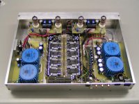
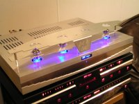
Today I completed most of the D-I 8 housing (tube protection grille and top cover). Here is the first photograph. I had to use plenty of ventilation slots to avoid too high temperatures. I fitted heatsinks on the TDA1541A DACs using spring clamps and silver-based heatsink compound, this way the heatsinks can be removed easily if desired.
The tube protection grille is fixed to the top cover, when the top cover is removed, all parts can be easily accessed.
Hi all,
Project update,
Today I completed most of the D-I 8 housing (tube protection grille and top cover). Here is the first photograph. I had to use plenty of ventilation slots to avoid too high temperatures. I fitted heatsinks on the TDA1541A DACs using spring clamps and silver-based heatsink compound, this way the heatsinks can be removed easily if desired.
The tube protection grille is fixed to the top cover, when the top cover is removed, all parts can be easily accessed.
Attachments
LM4562 tested
Hi stefanobilliani,
Thanks for your reply [post#1176]
The 48 KHz output of the mac works fine with the D-I DAC's already (the D-I DAC's have no problem with 48KHz). The CS8416 arrived, so I can start with the universal I2S prototype soon, the CS8416 is specified for max. 192KHz. This interface enables connecting most digital sound sources to the D-I DAC's. A bypassable shift-register reclocker will take care of jitter, providing optimal performance, when synchronous reclocking isn't possible. Yes, the shift-register reclocker proves to be a universal jitter remover and works very well with USB / SPDIF sources.
> The ferrite beads (filters) are used to block RF currents, keeping the signal path for RF currents as short as possible. The D-I 8 core has voltage regulators placed close to the DAC's and OP-amps, already keeping the signal path for RF currents short, the filters on the analog main-board (one for every power supply pin), will block RF signals in both directions (L-C-L filter).
The D-I 16 can be optimized by adding these filters, I will have a look if I can add them to the existing PCB lay-out.
> The professional PCB's will basically be the same as the tested prototype PCB's. The D-I 8 mainboard already has a large ground plane, as do all modules placed on it. I think it's possible to get good results with double sided PCB's.
All PCB's will be either single sided (D-I 16 power supply) or double sided.
I also received some LM4562's today, metal can, dip and SO8 housing. I placed the metal can version in the D-I 8 I/V stage first, they get very hot because they have to drive approx. 4.5V DC in 590 Ohms (TDA1541A offset current), so I milled a special heatsink for it. Sound quality is really something else, seems the D-I 8 has not nearly reached its optimal performance. The LM4562 metal can's provide extreme transparent sound in the mixed mode, very accurate bass and are much cleaner sounding than the OPA627. The effect of adding a tube amplifier now becomes ever so clear, it adds warmth and depth to the sound that just wouldn't be possible by just forcing the LM4562 in class A.
Next I put the DIP version of the LM4562 in my control amplifier (used the OPA627 before), this was a revelation. Note, I was testing with the USB interface! all I can say is that the shift-register reclocker does miracles to the sound quality. Now with the LM4562 it becomes clear how well this reclocker performs.
So both the D-I 8 and D-I 16 will now be equipped with the LM4562 (I prefer the metal can version). I will modify the PCB lay-out so a dual version like the LM4562 can be used without adapters (single OPA627 DIP version is used here now).
Next is testing a cascode bias circuit that forces the LM4562 (diff amp) in class A, but keeps the bias current constant, regardless of the output voltage. This will suppress power supply noise on the OP-amp output as well. The cascode bias circuit seems to give superior performance over a plain 5K resister from output to minus. The cascode circuit will consist of only 2 J-FET's and 2 resistors.
I also did a lot of experimenting with DAC temperature, TDA1541A's get very hot, as they dissipate up to 1W each (8W in total). So the chip temperature get's very high. Chip Housing temperature already goes up to approx. 68 degrees centigrade in a average housing at 20 degrees centigrade ambient temperature. More heat also means more noise / drift, so I made a special heatsink construction that routes the heat from all 8 DAC chips to the aluminum housing, keeping all DAC chip's temperature around 50 degrees centigrade. It also provides thermal coupling between all 8 DAC chip's. The sound is clearer now, even more detail. The additional cooling also extends DAC chip life (very important when using double crowns).
heatsink 1
Hi all,
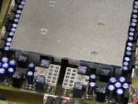
A picture of the LM4562 heatsink used in the D-I 8, it's milled form 3mm thick aluminum and clamped on the LM4562.
The large heatsink in the back is used to cool the 8 TDA1541A's. About 8...10W of heat is produced here that needs to be dissipated by the large aluminum housing (top and rear cover).
Hi all,
A picture of the LM4562 heatsink used in the D-I 8, it's milled form 3mm thick aluminum and clamped on the LM4562.
The large heatsink in the back is used to cool the 8 TDA1541A's. About 8...10W of heat is produced here that needs to be dissipated by the large aluminum housing (top and rear cover).
Attachments
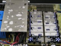
Heatsink 3
Hi all,
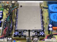
A photograph of the disassembled TDA1541A heatsink. There is a separate aluminum block mounted on each TDA1541A module, it's clamped to the chip using a modified sub-D cable clamp. Heatsink compound is used for optimal contact between chip housing and aluminum block.
Next the large aluminum heatsink is mounted on top of these aluminum blocks, again using heatsink compound (I will use more when the heatsinks are annodized). Finally this heatsink is mounted to the rear cover, now the heat from the TDA1541A's can be dissipated on the rear and top cover of the aluminum housing.
This effort results in lower noise / more detail and extended TDA1541A life by keeping temperatures lower. The heat produced is not caused by paralleling nor by DEM reclocking, tests were done using a single TDA1541A, with only 1 I/V stage connected and a 470pF DEM clock oscillator capacitor, heat dissipation was similar.
Hi all,
A photograph of the disassembled TDA1541A heatsink. There is a separate aluminum block mounted on each TDA1541A module, it's clamped to the chip using a modified sub-D cable clamp. Heatsink compound is used for optimal contact between chip housing and aluminum block.
Next the large aluminum heatsink is mounted on top of these aluminum blocks, again using heatsink compound (I will use more when the heatsinks are annodized). Finally this heatsink is mounted to the rear cover, now the heat from the TDA1541A's can be dissipated on the rear and top cover of the aluminum housing.
This effort results in lower noise / more detail and extended TDA1541A life by keeping temperatures lower. The heat produced is not caused by paralleling nor by DEM reclocking, tests were done using a single TDA1541A, with only 1 I/V stage connected and a 470pF DEM clock oscillator capacitor, heat dissipation was similar.
Attachments
 Due to the close setup? A single dac doesn't get that warm here.
 I read at least a year ago here that a lot of 1541A-based DACs were having problems and got the chip to start getting really hot and eventually fail. If they get hot, it's because there's a design problem, and if John has this particular problem, he could fry 8 1541As with time.
Not sure, but I think that it's PSU related.
1541A doesn't/shouldn't have the wearout problem like TDA1540 and early 1541 chips. BUT, a lot of people with the chips getting hot report that they fail with time.
Note : I'm not sure about all this, I just think I remember to have read this in various posts now in the archives.
Hi John ")
I had similar experience with LM4562 in SMD (MA?), both as output opamp of a cheap DVD that I'm modding (while your kits are ready ) and as input opamp of UCD180 class D amps.
They are very transparent and detailed, with soft and elegant highs. Much better than NE5532 and JRC46XX opamps that they replaced. With some partner gear they can sound thin on midrange and bass light. But with some other partners they sound terrific; great inner detail
For your high Tº issue, I planned for the D-I 16 a vertical position of the PCB and vertically oriented heatsinks to allow for convective cooling I don't mind having a tall box...
I see your present D-I 8 PCB is crowded and probably holes won't fit to allow air cooling.
Cheers,
M
I had similar experience with LM4562 in SMD (MA?), both as output opamp of a cheap DVD that I'm modding (while your kits are ready
) and as input opamp of UCD180 class D amps.They are very transparent and detailed, with soft and elegant highs. Much better than NE5532 and JRC46XX opamps that they replaced. With some partner gear they can sound thin on midrange and bass light. But with some other partners they sound terrific; great inner detail
For your high Tº issue, I planned for the D-I 16 a vertical position of the PCB and vertically oriented heatsinks to allow for convective cooling
I don't mind having a tall box...I see your present D-I 8 PCB is crowded and probably holes won't fit to allow air cooling.
Cheers,
M
Hi tubee,
Thanks for your reply [post #1190]
The TDA1541A's get hot because:
1) There is approx. 40 watts being dissipated (DAC 20W, tube amp 20W) causing the temperature inside the housing to rise (approx 40 degrees centigrade).
2) The D-I 8 core has to dissipate a lot of power on a small area.
The TDA1541A's are not malfunctioning, power supplies are within 1.5% tolerance, the DAC chip's function correctly.
The D-I 8 and D-I 16 are exeptional designs that introduce some unexpected problems to solve, like the higher temperatures.
The very compact housing creates thermal problems that need to be solved, don't forget the D-I 8 housing only measures 5 X 32 X 42 cm! Removing the D-I 8 top cover, reduces TDA1541A temperature.
The most effective way is to transport most of the heat away from the inside of the housing. So I took the part that certainly shouldn't overheat (D-I 8 core) and used a heatsink construction that draws the heat away from the TDA1541A chips and dissipates it on the aluminum housing. I can't use a fan of course, so the only options are convection cooling and thermal conduction.
The TDA1541A datasheets specify the following typical max. currents:
+5V 40mA (0.2W), -5V 50mA (0.25W), -15V 35mA (0.52W), total: 0.97W. 8 * TDA1541A use 8 * 0.97W = 7.76W.
The high temperatures of the LM4562 in the I/V stage can be easily explained, due to the offset currents of 4 DAC chip's the LM4562 output voltage will be approx. 5V DC, the load is the 590 Ohm I/V resistor to virtual ground, causing a DC current of approx. 8.5mA at 15V, adding approx. 0.12W power consumption. So a dual LM4562 consumes approx. 0.24W more now, and needs a heatsink.
Next there is the differential setup, one DAC group receives a inverted data signal, causing all DAC chips in this group generating higher average output currents than the NON-inverted group. So theoretically the inverted DAC group would dissipate slightly more power.
The ambient temperature inside a housing is often underestimated, even with sufficient ventilation slots, air movement is slow, effectively causing it to isolate, causing heat build-up. With the top cover removed, temperatures drop significantly. The larger the housing, the better air can circulate and cools down components.
The D-I 16 dissipates approx. 15 watts in total. The TDA1543 are located close to the bottom of the housing (lower temperatures) and don't get so hot. But I am also thinking of adding a heatsink here, just in case.
Hi John,
Wouldn't copper heat sink work better than aluminum? Also, instead of solid aluminum top cover, couldn't you use a widely spaced wire mesh with holes just small enough so that a human finger can't get throuh? If designed well, the wire mesh could look quite attractive.
Wouldn't copper heat sink work better than aluminum? Also, instead of solid aluminum top cover, couldn't you use a widely spaced wire mesh with holes just small enough so that a human finger can't get throuh? If designed well, the wire mesh could look quite attractive.
If designed well, the wire mesh could look quite attractive.
... and accumulate lots and lots of dust.
Best regards,
Sander Sassen
http://www.hardwareanalysis.com
- Home
- Source & Line
- Digital Line Level
- Building the ultimate NOS DAC using TDA1541A