SSassen said:rfbrw,
In post #130 (page 13) you wrote the following:
How'd that work exactly? What you're suggesting is you'd need some logic before the DAC to interpolate the various values and then simply run the DAC at 4Fs or 8Fs, right? Isn't that awfully close to simply using a oversampling digital filter?
Best regards,
Sander Sassen
http://www.hardwareanalysis.com
You can use the same techniques as those found in a digital filter, it is just a matter of weighting the coefficients correctly but you will loose the original 16 bit wordlength.
What I was referring to was hardware oversampling using two dacs per channel, each running at 4Fs, as opposed to eight at Fs. I suppose the advantage to this kind of oversampling, particularly if one prays at the Church of Nos, is the avoidance of long wordlengths and the need to dither down to 24 bits or less.
Rfbrw,
Well, since it looks like I'll be building this DAC, as I just ordered 16-pcs of TDA1541A, or something that uses TDA1541A in some way, shape or form, I'm all for a bit of experimenting. My box of parts has ample supply of DF1704 as well as SRC4192, so if you have some fun ideas to try out I'll be your testcase so to speak, just let me know what you have in mind and I'll build it.
Ps. Oh, and I do have access to an AP System 2, so measurements etc. are not a problem.
Best regards,
Sander Sassen
http://www.hardwareanalysis.com
Sander,
I think it is interesting...
Hi Sander,
IMHO it would be the same problem as with the DI DAC, there are small timing intervals on the summing junction and jitter may be an issue.
Also the os filter is involved and I want to avoid that.
I found that with TDA1541A and PCM56 in non os there is dominant even order distortion if there is any.
With 4x and 8x os filters the odd orders are dominant. Ughh !
Now I am not sure if non os gives even orders and all os gives odd orders, or if odd os rates give even orders and even os rates give odd orders.
Regards, Bernhard
Now, what happens with the 8x linear interpolation ?, even or odd orders ???
I think it is interesting...
This is a message from SSassen at diyAudio Forums ( http://www.diyaudio.com/forums/index.php
).
This is the message:
Hi Bernhard,
I couldn't help but notice your below post:
"Another variation of linear interpolation came to my mind, did not think it
through...
It could use a 8x os filter to produce "good" new samples.
A decade counter distributes the samples to 8 DACs in a ring configuration.
The result is a data update rate of 44,1 kHz for each DAC like in non os, and
overlap of the DACs is the same as with linear interpolation but it uses true (
interpolated )samples.
Any good ?"
Care to elaborate? Sounding interesting enough to me.
Cheers,
Sander Sassen.
Hi Sander,
IMHO it would be the same problem as with the DI DAC, there are small timing intervals on the summing junction and jitter may be an issue.
Also the os filter is involved and I want to avoid that.
I found that with TDA1541A and PCM56 in non os there is dominant even order distortion if there is any.
With 4x and 8x os filters the odd orders are dominant. Ughh !
Now I am not sure if non os gives even orders and all os gives odd orders, or if odd os rates give even orders and even os rates give odd orders.
Regards, Bernhard
Now, what happens with the 8x linear interpolation ?, even or odd orders ???
Bernhard,
Well, those can be cancelled, or at least significantly reduced, if a balanced configuration is used, that's what I'll do anyway, as all my equipement is balanced. Odd order is what I worry about though.
Best regards,
Sander Sassen
http://www.hardwareanalysis.com
I found that with TDA1541A and PCM56 in non os there is dominant even order distortion if there is any.
Well, those can be cancelled, or at least significantly reduced, if a balanced configuration is used, that's what I'll do anyway, as all my equipement is balanced. Odd order is what I worry about though.
Best regards,
Sander Sassen
http://www.hardwareanalysis.com
MGH,
I ordered a few spares, so I can manually select them for lowest distortion and use the best DACs for the final version.
Best regards,
Sander Sassen
http://www.hardwareanalysis.com
I think you can only use 8 TDA1541A for the D-I DAC. The 16 chip version is only for the TDA1543. Unless you plan on building two D-I 8 DACs.
I ordered a few spares, so I can manually select them for lowest distortion and use the best DACs for the final version.
Best regards,
Sander Sassen
http://www.hardwareanalysis.com
John et al,
I was planning on using the CD-Pro2M I bought a few months ago to interface directly with this DAC, but after having read the datasheet of the chipset used on the CD-Pro2M I'm wondering whether it is compatible?
Below image details what format the chipset is able to output through its SCLK, DATA and WCLK pins. It apparantly uses a 2.116MHz SCLK, which is different from the 2.82MHz SCLK normally used with a TDA1541A or the I2S protocol. I have access to all these different protocols due to the use of proprietary controller for the CD-Pro2M.

Any suggestions? Or am I better off trying a different approach, if so, which one?
Best regards,
Sander Sassen
http://www.hardwareanalysis.com
I was planning on using the CD-Pro2M I bought a few months ago to interface directly with this DAC, but after having read the datasheet of the chipset used on the CD-Pro2M I'm wondering whether it is compatible?
Below image details what format the chipset is able to output through its SCLK, DATA and WCLK pins. It apparantly uses a 2.116MHz SCLK, which is different from the 2.82MHz SCLK normally used with a TDA1541A or the I2S protocol. I have access to all these different protocols due to the use of proprietary controller for the CD-Pro2M.
Any suggestions? Or am I better off trying a different approach, if so, which one?
Best regards,
Sander Sassen
http://www.hardwareanalysis.com
Rfbrw,
Oh, I'm confident it will work, I'm just curious as to why the clockspeed is different from what I've seen previously. Let me rephrase the question, or rather questions, as there's actually two questions in my previous post.
1. Why is the SCLK (BCK) different from what is usually seen in older CD-players, ie. a 2.82MHz SCLK (BCK)?
2. What do we gain, or lose, by the reduction in SCLK (BCK) clockspeed?
Best regards,
Sander Sassen
http://www.hardwareanalysis.com
Rfbrw,
Wait a minute, I think I know what they did here. With a 2.82MHz BCK there's 2.82e+06/44.1e+03 = 64, hence 64 BCK clocks in one LRCLK. With a 2.1168MHz BCK, there's 2.1168+06/44.1e+03 = 48, hence 48 BCK clocks in one LRCLK. But why? Is this Philips CDPro2M using the Sony I2S format? Sure looks like it.
Best regards,
Sander Sassen
http://www.hardwareanalysis.com
Rfbrw,
My bad guess I missed a few posts whilst reading this thread, your post #470 details this problem exactly, so I'll be changing taps on the shift registers it seems.
http://www.diyaudio.com/forums/showthread.php?postid=951744#post951744
Why Philips would use this format rather than their own is beyond me, have they gone &*%*%$&^%$ nuts?
Best regards,
Sander Sassen
http://www.hardwareanalysis.com
My bad
guess I missed a few posts whilst reading this thread, your post #470 details this problem exactly, so I'll be changing taps on the shift registers it seems.The Sony format can be converted to the I2S format with a shift register. I2S doesn't care about BCK so long as there is at least one BCK cycle per bit. 64 cycles is more an artifact of a digital receiver in master mode. A poster by the name of cm put forward such a circuit a while ago.
So you have three choices. Change the shift register taps to suit the convert to the I2S format and change the taps to suit 48Fs(easy). Build the logic needed to move data from the 48Fs domain to the 64Fs domain(resource intensive). Use SPDIF. Left out the use of an ASRC as I would thought it defeat the object of the excercise.
http://www.diyaudio.com/forums/showthread.php?postid=951744#post951744
Why Philips would use this format rather than their own is beyond me, have they gone &*%*%$&^%$ nuts?
Best regards,
Sander Sassen
http://www.hardwareanalysis.com
SSassen said:
Why Philips would use this format rather than their own
They use it because it is their format. I2S, like many other formats does not care about BCK, so long as there are enough cycles to load the input register of the following device. The only format that fixes BCK is the Sony format, at 48Fs. Since I2S will support any BCK frequency from 32Fs and up, it seems logical that to run everything at 48Fs.
New D-I 8 operational
Hi all,
Project update,
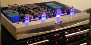
Today I managed to squeeze the entire D-I 8 DAC in a 42 X 5 X 32cm housing! I added a picture of the new D-I 8 DAC, when it was just connected to the large set for testing.
The tube status LED's and logo are blue on this one, but many different colors can be chosen. It uses the same optics for logo lighting. Can't wait to see this one with annodized housing.
I used 25VA torroid transformers as the 15VA ones were not in stock.
Like with the D-I 16, a step pattern is milled in a aluminum profile and a high-gloss stainless steel sheet is used.
The tube protection grid will be something special, I plan designing and milling it tomorrow.
Oh yes, the D-I 8 works fine, and is much easier to assemble than the octal D-I DAC. All PCB's are mounted on the bottom plate. I will make some more detailed pictures tomorrow, showing the new tube PCB's and power supply PCB's. As noted, all power supplies now have skottky diodes to minimize noise. The high-voltage supply uses soft recovery types.
As for the format issue with the CDPRO2, I am already planning to make a SMD based auto-detecting timing-chain PCB that just plugs in the D-I 8, the D-I 16 probably comes in two formats 64 BCK and 48 BCK version. I also plan to buy a CDPRO2 to make absolutely sure it works flawless.
I am also planning to design the new digital interface converter soon, based on the CS8416. This is mainly intended to enable SPDIF sources to be connected the D-I 8 and D-I 16, the interface provides both synchronous reclocking and a shiftregister reclocker for optimal sound quality.
I am still waiting for my LM4562 samples, so I haven't been able to test this OP-amp yet.
Hi all,
Project update,
Today I managed to squeeze the entire D-I 8 DAC in a 42 X 5 X 32cm housing! I added a picture of the new D-I 8 DAC, when it was just connected to the large set for testing.
The tube status LED's and logo are blue on this one, but many different colors can be chosen. It uses the same optics for logo lighting. Can't wait to see this one with annodized housing.
I used 25VA torroid transformers as the 15VA ones were not in stock.
Like with the D-I 16, a step pattern is milled in a aluminum profile and a high-gloss stainless steel sheet is used.
The tube protection grid will be something special, I plan designing and milling it tomorrow.
Oh yes, the D-I 8 works fine, and is much easier to assemble than the octal D-I DAC. All PCB's are mounted on the bottom plate. I will make some more detailed pictures tomorrow, showing the new tube PCB's and power supply PCB's. As noted, all power supplies now have skottky diodes to minimize noise. The high-voltage supply uses soft recovery types.
As for the format issue with the CDPRO2, I am already planning to make a SMD based auto-detecting timing-chain PCB that just plugs in the D-I 8, the D-I 16 probably comes in two formats 64 BCK and 48 BCK version. I also plan to buy a CDPRO2 to make absolutely sure it works flawless.
I am also planning to design the new digital interface converter soon, based on the CS8416. This is mainly intended to enable SPDIF sources to be connected the D-I 8 and D-I 16, the interface provides both synchronous reclocking and a shiftregister reclocker for optimal sound quality.
I am still waiting for my LM4562 samples, so I haven't been able to test this OP-amp yet.
Attachments
Hi,
Very nice work, EC. It resembles the surface of the "Star of Death" from "Star wars"
 from here...
I2S: we all remember and thank that rfbrw warned us about this "little inconvenient" with the very good CDPRO. As I also remember, EC "promised" an autodetecting circuit for this two BCK forms. Now if the 48BCK D-16 is feasible, it could be a better option, with probably less parts involved (?)
The other option is starting reading data sheets from other digital decoder chips from other (maybe cheap) players and extract from there the I2S output
Regards,
M
Very nice work, EC. It resembles the surface of the "Star of Death" from "Star wars"
from here...I2S: we all remember and thank that rfbrw warned us about this "little inconvenient" with the very good CDPRO. As I also remember, EC "promised" an autodetecting circuit for this two BCK forms. Now if the 48BCK D-16 is feasible, it could be a better option, with probably less parts involved (?)
The other option is starting reading data sheets from other digital decoder chips from other (maybe cheap) players and extract from there the I2S output
Regards,
M
Re: New D-I 8 operational
Hello ecdesigns .
It would be -very nice - if possible , to be able to manage with 48khz signals to watch dvd s with the D-I .
I want to use ferrite beads for filtering and decoupling chips on board . Do you consider theyr use , and if not do you think it will be easy to adapt they on your boards ?
Also , will your professional board(s) include ground plane(s) ?
Thanks ,
Stefano
-ecdesigns- said:Hi all,
I am also planning to design the new digital interface converter soon, based on the CS8416. This is mainly intended to enable SPDIF sources to be connected the D-I 8 and D-I 16, the interface provides both synchronous reclocking and a shiftregister reclocker for optimal sound quality.
Hello ecdesigns .
It would be -very nice - if possible , to be able to manage with 48khz signals to watch dvd s with the D-I .
I want to use ferrite beads for filtering and decoupling chips on board . Do you consider theyr use , and if not do you think it will be easy to adapt they on your boards ?
Also , will your professional board(s) include ground plane(s) ?
Thanks ,
Stefano
Death Star
Hi maxlorentz.
Is this your sub?
http://img.engadget.com/common/images/4181077119819632.JPG?0.15358529731517667
Hi maxlorentz.
Is this your sub?
http://img.engadget.com/common/images/4181077119819632.JPG?0.15358529731517667
stefanobilliani said:Well, talking about BCK = 48fs there is not just CD pro avaiable out there :
Philips CD723 and Marantz CD67 are 2 fine examples also .
Hi,
how is with CD 304 mkII Philips player? Is the same 48fs or more?
regards, bostjan
tubee said:CD304mk2 = 64 BCK cycles, works on 2.8Mhz (11.2896 / 4)
Is your modding done Borstjan?
Hi Tubee,
i didnt made all mods, i playing with SKA amplifier.
Waiting also for DI-octal DAC PCBs. I bought this player mostly because of this.
What I did:
* changing all caps around chips (mostly OS-CONs)
* Op-amp changed to LM4562 put in A-class (make very nice sound better than OP627)
* around TDA1541A changed 14 SMD caps to 100nF BC (which Ec-design sugestion - using , makes big difference)
Plan: DEM reclocking
Has anyone output schematic for CD304mk2?
regards, Bostjan
- Home
- Source & Line
- Digital Line Level
- Building the ultimate NOS DAC using TDA1541A