Hi John. You have been busy again! Thanks for elaborating the diy resistors. I have some enamelled wire to try this. When 1 meter has 9 ohm's you used is very thin wire then, 0.05 mm or so.
Then i will not use this idea, too risky for me, thanks for info.
Off topico againo:
I just did some other try-outs:
Added remote controlled volume control in pre-amp: A 433Mhz signal from a on-off mains switches (12Eu at the shop "Action") switches a 74/08 port and H bridge to a DC motor. This motor and gear is scavenged from video player. With a clutch (otherwise it ruins the pot) it drives the axle. Nice to regulate volume into the listening chair!
Replaced in tubed pre amp the 10uF MKP audyn caps in big 6.8uF Audyn cap "plus" caps. Good depth and detail, less colouration, but i lost some bass, and i like bass. Mids has now a slight distorted "edge" on it. So still not fully satisfied. This cap also shows the weak spots of my speakers more obvious (2 way: cone break up) They costed me Eu 17.50 each.
Another mod: replaced the very old, thick & stiff (low voltage cable for trucks) speakerwire into 24 awg Cat5 cable, 3 cables parallel woven by myself. Used solid core type. Whole other sound again. Bass is some better now (thinner effective cable diameter) but also have some mild enhancement of midbass. Depth is not that obvious anymore. But treble is much cleaner now, this cat 5 cable is every penny worth for the cost of it! (8 euro for 18m)
See also:
http://www.humblehomemadehifi.com/CAT5.html
Also keep in mind that a tube faillure could cause all TDA1541A's connected to be permanently damaged.
Then i will not use this idea, too risky for me, thanks for info.
Off topico againo:
I just did some other try-outs:
Added remote controlled volume control in pre-amp: A 433Mhz signal from a on-off mains switches (12Eu at the shop "Action") switches a 74/08 port and H bridge to a DC motor. This motor and gear is scavenged from video player. With a clutch (otherwise it ruins the pot) it drives the axle. Nice to regulate volume into the listening chair!
Replaced in tubed pre amp the 10uF MKP audyn caps in big 6.8uF Audyn cap "plus" caps. Good depth and detail, less colouration, but i lost some bass, and i like bass. Mids has now a slight distorted "edge" on it. So still not fully satisfied. This cap also shows the weak spots of my speakers more obvious
(2 way: cone break up) They costed me Eu 17.50 each. Another mod: replaced the very old, thick & stiff (low voltage cable for trucks) speakerwire into 24 awg Cat5 cable, 3 cables parallel woven by myself. Used solid core type. Whole other sound again. Bass is some better now (thinner effective cable diameter) but also have some mild enhancement of midbass. Depth is not that obvious anymore. But treble is much cleaner now, this cat 5 cable is every penny worth for the cost of it! (8 euro for 18m)
See also:
http://www.humblehomemadehifi.com/CAT5.html
Coupling cap's
Hi Tubee,
Thanks for your reply [post#1021]
Yes I use very thin copper wire in order to keep the mobius loop as short as possible, this reduces the parallel capacitance.
Well, nice creative remote volume control construction.
The coupling cap's are not off topic as they are used in the tube output of the octal D-I DAC as well and have a significant effect on sound quality. Can you understand now why I use DC coupling in my audio set, and made the octal D-I DAC DC coupled exept for the single coupling capacitor in the tube output? The Audyn caps work very well in speaker crossover filters, but even the Audyn plus is not optimal for tweeters, you need a tin capacitor to get optimal resolution and detail. But it seems they are not optimal for use as coupling capacitors in a tube amplifier. A good coupling capacitor for this application would be Auricap (you can order them from Automatic Electric Europe).
If a speaker get's damaged that easily, perhaps the crossover filter is not optimal.
Yes, I have seen the network cable speaker cables already. I use 24 solid core enamelled copper wires twisted to one wire, there is a photograph of it on my website. I can only confirm that they result in a much better sound quality.
USB interface
Hi Zoran,
Thanks for your reply [post#1022]
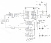
If I am correct, I already posted a diagram of the shiftregister reclocker. But I haven't posted the complete schematics of the USB interface yet. So I added the schematics, it's a straight forward bus powered setup using the PCM2706, but it uses the shiftregister reclocker, differential buffered I2S outputs and a common 48 MHz crystal oscillator module. If you want single ended I2S outputs, you can use the differential receivers that are also located within the DS8921 and DS8922 chips. It's preferred to always use these buffers as the PCM2706 can damage easily when the output's aren't buffered.
For single ended outputs, connect the following pin's on the DS8921:
pin 6 connected to pin 8 only DO+ to RI+ (pin 8 NOT connected to GND)
pin 5 connected to pin 7 only DO- to RI- (pin 7 NOT connected to VCC)
pin 2 is BCK output.
connect the following pin's on the DS8922:
pin 14 to pin 16 only DO1+ to RI1+ (pin 16 NOT connected to GND)
pin 13 to pin 15 only DO1- to RI1- (pin 15 NOT connected to VCC)
pin 1 is WS output
pin 12 to pin 10 only DO2- to RI2- (pin 10 NOT connected to VCC)
pin 11 to pin 9 only DO2+ to RI2+ (pin 9 NOT connected to GND)
pin 8 is DATA output
Hi Zoran,
Thanks for your reply [post#1022]
If I am correct, I already posted a diagram of the shiftregister reclocker. But I haven't posted the complete schematics of the USB interface yet. So I added the schematics, it's a straight forward bus powered setup using the PCM2706, but it uses the shiftregister reclocker, differential buffered I2S outputs and a common 48 MHz crystal oscillator module. If you want single ended I2S outputs, you can use the differential receivers that are also located within the DS8921 and DS8922 chips. It's preferred to always use these buffers as the PCM2706 can damage easily when the output's aren't buffered.
For single ended outputs, connect the following pin's on the DS8921:
pin 6 connected to pin 8 only DO+ to RI+ (pin 8 NOT connected to GND)
pin 5 connected to pin 7 only DO- to RI- (pin 7 NOT connected to VCC)
pin 2 is BCK output.
connect the following pin's on the DS8922:
pin 14 to pin 16 only DO1+ to RI1+ (pin 16 NOT connected to GND)
pin 13 to pin 15 only DO1- to RI1- (pin 15 NOT connected to VCC)
pin 1 is WS output
pin 12 to pin 10 only DO2- to RI2- (pin 10 NOT connected to VCC)
pin 11 to pin 9 only DO2+ to RI2+ (pin 9 NOT connected to GND)
pin 8 is DATA output
Attachments
adhoc said:Anyone else have anything to say regarding software resampling?
My impression was that it was to be avoided in general not only because it used a lot of CPU, but also because the results were often less than satisfactory, especially when compared to hardware resampling.
What sort of resampling algorithm does the Mac use? PPHS? SSRC? LI?
I have found SRC upsampling with a PC to be superior to all other formats, given that the optimum ASIO is used with it. I use:
Foobar 0.8.3
ASIO SSE3 vers. 47a
SRC
All of my customers that use MAC have reported that the MAC upsampling does not sound as good as the 16/44.1 output.
Steve N.
Empirical Audio
Manufacturer
Coupling cap
Hi John
I just decided that tomorrow i will refit the old standard 10uF MKP Audyncaps back again in the tube preamp. They where paralled with KS, but now i will do that with some small PIO's .I'm not satisfied with the sound of the "plus". Some closed in and a distorted edge in mids, treble seems cleaner, but also softer, and not " fresh". The Plus has 2 windings in series, that must be the problem, to many borders to cross or something.
Indeed found out a cap for tweeters works totally different then as coupling, in special in tubed amps. It has to keep 110V DC away of my preamp.
I will order 2 caps from AE in Schagen, see how they perform.
Btw, my tweeters are filtered with huge metal can 3.4uF PIO's from a tube light of the seventies!
I have at the moment a Quad 33 and 303 to service, some small problems. The sound is rather good, very clean highs. But soundstage is flat(transistor + lytic coupling cap to speakers)
Coupling cap 2
Refitted the standard Audyncaps; yes, thats more like it.
In meantime swapped the Panasonics in cathode of phonostage in Standard black Gates. I was sceptic about BG's, but now i am a believer too: This cap is a lot better than any other lytic. So John if you search a good cap for cathodedecoupling in your tubestage...
And someone interested in 2 MKP Audyn Cap "plus" caps6.8uF 425AC 800V DC?
K4040 mods
Hi Tubee,
Thanks for your reply [post#1027 / #1028]
Little bit off topic here, since you are talking about tube amplifiers, guess what I have been doing? I needed a tube amplifier to test both the sonic resonators and the octal D-I DAC, but I didn't have one. I didn't want to spend a lot of money on a High-End tube amplifier, and there wasn't time to design one from scratch, so I decided to buy a K4040 kit (shame on me). I knew there were some design problems, and I might need to do some minor modding in order to get the sound right. Some JJ KT77's were ordered, just in case...
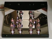
Then the kit arrived, it didn't have the ILP transformers I hoped for, the EL34's were from Svetlana, the ECC83's from Sovtec and the ECC82 from Electro Harmonics. The housing looked very impressive with the massive chrome plates, even the feet and the decoration rings for the tubes were chrome. It comes with a a huge single-sided PCB. I planned to use Beyschlag metal film resistors instead of the cheap carbon resistors, Spectrol cermet's for bias adjustment and Panasonic electrolytic capacitors. After a few hours the PCB was assembled, wiring the EL34 sockets cost a lot of time. Then it took me another day to squeeze-in the transformers and wiring as there was very little space.
I continued with the bias adjustment, there is a LED indicator for this, but it's readout wasn't very good, a lot of LED's burning and flashing at the same time, so I had to solder a 100nF across the LM3914 input to get it working correctly. Finally it was time to listen to this 2 X 90W rms tube monster, well in fact the sound it produced wasn't that good. Perhaps the Svetlana's needed some burning-in time, but after burning-in one full day without significant sound improvement I lost my patience. Measurements showed relatively high distortion and a huge peak at around 40KHz.
Next lot's of different tube brands were tested, but it became clear to me, the design wasn't optimal, so I could prepare myself for some serious modding. Starting with the input stage, what's a ECC82 doing here? I replaced it with a JJ ECC83 and changed the resistor values for maximum linear drive. A concertina phase splitter using a ECC83 to drive 4 X EL34 ?? out it went and replaced with a modified Schmitt phase splitter with a constant current source (2 X J508 in parallel) to ensure fully symmetrical drive. The ECC83 wasn't capable of driving 4 EL34's, so I replaced it with JJ ECC81. The EL34's were replaced with JJ KT77, next the 22nF coupling cap's were replaced with LCR 100nF/1KV polypropylene capacitors, yes tubee, coupling cap's can make a world of difference. Oh yes, the overall feedback was removed, only using local feedback. The bias voltage was stabilized with a 47V zenerdiode (22K series resistor lowered to 10K).
After these modifications there wasn't much left of the original K4040 design, but the sound quality was stunning, what a difference. The K4040 turned into a beautiful sounding High-End power amplifier. Distortion is much lower, it sounds crystal clear, transparent and open, with a deep impressive bass and a wonderful sounding midrange. Unbelievable what a few modifications can do. By the way, the sonic resonators work very well with this tube amplifier, same with the octal D-I DAC. I added a photograph of this modded K4040.
Beside from this K4040 intermezzo, I also spend a lot of time on the octal D-I DAC, the housing is ready now (side panels and ventilation slots in the top cover) so it can be annodized. The PCB's are almost verified, so a small batch of PCB's can be ordered soon.
Hi Tubee,
Thanks for your reply [post#1027 / #1028]
Little bit off topic here, since you are talking about tube amplifiers, guess what I have been doing? I needed a tube amplifier to test both the sonic resonators and the octal D-I DAC, but I didn't have one. I didn't want to spend a lot of money on a High-End tube amplifier, and there wasn't time to design one from scratch, so I decided to buy a K4040 kit (shame on me). I knew there were some design problems, and I might need to do some minor modding in order to get the sound right. Some JJ KT77's were ordered, just in case...
Then the kit arrived, it didn't have the ILP transformers I hoped for, the EL34's were from Svetlana, the ECC83's from Sovtec and the ECC82 from Electro Harmonics. The housing looked very impressive with the massive chrome plates, even the feet and the decoration rings for the tubes were chrome. It comes with a a huge single-sided PCB. I planned to use Beyschlag metal film resistors instead of the cheap carbon resistors, Spectrol cermet's for bias adjustment and Panasonic electrolytic capacitors. After a few hours the PCB was assembled, wiring the EL34 sockets cost a lot of time. Then it took me another day to squeeze-in the transformers and wiring as there was very little space.
I continued with the bias adjustment, there is a LED indicator for this, but it's readout wasn't very good, a lot of LED's burning and flashing at the same time, so I had to solder a 100nF across the LM3914 input to get it working correctly. Finally it was time to listen to this 2 X 90W rms tube monster, well in fact the sound it produced wasn't that good. Perhaps the Svetlana's needed some burning-in time, but after burning-in one full day without significant sound improvement I lost my patience. Measurements showed relatively high distortion and a huge peak at around 40KHz.
Next lot's of different tube brands were tested, but it became clear to me, the design wasn't optimal, so I could prepare myself for some serious modding. Starting with the input stage, what's a ECC82 doing here? I replaced it with a JJ ECC83 and changed the resistor values for maximum linear drive. A concertina phase splitter using a ECC83 to drive 4 X EL34 ?? out it went and replaced with a modified Schmitt phase splitter with a constant current source (2 X J508 in parallel) to ensure fully symmetrical drive. The ECC83 wasn't capable of driving 4 EL34's, so I replaced it with JJ ECC81. The EL34's were replaced with JJ KT77, next the 22nF coupling cap's were replaced with LCR 100nF/1KV polypropylene capacitors, yes tubee, coupling cap's can make a world of difference. Oh yes, the overall feedback was removed, only using local feedback. The bias voltage was stabilized with a 47V zenerdiode (22K series resistor lowered to 10K).
After these modifications there wasn't much left of the original K4040 design, but the sound quality was stunning, what a difference. The K4040 turned into a beautiful sounding High-End power amplifier. Distortion is much lower, it sounds crystal clear, transparent and open, with a deep impressive bass and a wonderful sounding midrange. Unbelievable what a few modifications can do. By the way, the sonic resonators work very well with this tube amplifier, same with the octal D-I DAC. I added a photograph of this modded K4040.
Beside from this K4040 intermezzo, I also spend a lot of time on the octal D-I DAC, the housing is ready now (side panels and ventilation slots in the top cover) so it can be annodized. The PCB's are almost verified, so a small batch of PCB's can be ordered soon.
Attachments
Hi John
Nice to read about your Velleman kit experiences. I have been thinking to buy one too, but what i did till so far was a cheaper. I have a SE two EL36's in series amp design and part lying somewhere, it has to be finished. Tubed amps can give such fine sound, reasonable easy to modify. Yes a E83CC cannot drive everything, but has a large amplification factor. Allmost all old schematics use an ECC83 somewhere. Are endtubes in penthode?
Btw the Cat 5 cable sounds spacious, but not perfect. Maybe Supra cables?
Hi John!
I was reading your post (#1029) and it was very interesting. But there were a couple of things that were unclear to me. Could you please explain:
> what kind of a phase splitter a "Concertina phase splitter" is?
> what a "modified Schmitt phase splitter" looks like?
> could you please post a schematics of your modifications in the original circuit?
I am certain there are several people who would be interested in taking a look at them.
Thank you very much for your response.
have a nice one..
Alexiss
Octal D-I DAC taken apart...
Hi all,
Project update,
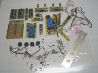
Yes I have been very busy, the octal D-I DAC is completely disassembled now in order to annodize the aluminum parts, I added a picture of its remains. I am already missing it's sound now, and would feel a lot better if it's re-assebled and working again.....
When looking at all the octal D-I DAC parts, it occured to me that it has become quite a complicated DAC with lot's of components, and the photograph doesn't even show the 37 CNC milled aluminum parts, only one aluminum duplicate part of the tube chassis. This results in relatively high cost and the necessary skills to build one. Still it's absolutely worth the effort, this becomes very clear when one has to listen to another DAC instead, it seems I am quite spoiled by the octal D-I DAC's sound quality.
I know the octal D-I DAC won't be cheap, so I started to figure out if it was possible to design a easy to build, small version D-I DAC, applying the same techniques used in the octal D-I DAC with a sound quality that comes as close as possible to the original octal D-I DAC prototype.
To keep the design compact and avoid high cost, the TDA1543 was selected. I already experimented with a TDA1543 based D-I DAC and even build a 32 X D-I DAC using this chip. The DAC will be based on 16 X TDA1543 in D-I mode, a op-amp I/V and diff amp. I obtained very good results with 2 X OPA627 for the diff amp and the AD823 as I/V converter.
The new D-I DAC will have a philips format timing-chain with 16 taps for DATA and 16 taps for WS. It will have a balanced DAC configuration like the octal D-I DAC to enable a DC-coupled output signal. It will accept either differential I2S or USB (optional). I will try to use a single PCB for this DAC, making it very easy to build. The housing dimensions will be approx. 32 X 15 X 5 cm. I will keep you all informed about this D-I DAC project.
Hi all,
Project update,
Yes I have been very busy, the octal D-I DAC is completely disassembled now in order to annodize the aluminum parts, I added a picture of its remains. I am already missing it's sound now, and would feel a lot better if it's re-assebled and working again.....
When looking at all the octal D-I DAC parts, it occured to me that it has become quite a complicated DAC with lot's of components, and the photograph doesn't even show the 37 CNC milled aluminum parts, only one aluminum duplicate part of the tube chassis. This results in relatively high cost and the necessary skills to build one. Still it's absolutely worth the effort, this becomes very clear when one has to listen to another DAC instead, it seems I am quite spoiled by the octal D-I DAC's sound quality.
I know the octal D-I DAC won't be cheap, so I started to figure out if it was possible to design a easy to build, small version D-I DAC, applying the same techniques used in the octal D-I DAC with a sound quality that comes as close as possible to the original octal D-I DAC prototype.
To keep the design compact and avoid high cost, the TDA1543 was selected. I already experimented with a TDA1543 based D-I DAC and even build a 32 X D-I DAC using this chip. The DAC will be based on 16 X TDA1543 in D-I mode, a op-amp I/V and diff amp. I obtained very good results with 2 X OPA627 for the diff amp and the AD823 as I/V converter.
The new D-I DAC will have a philips format timing-chain with 16 taps for DATA and 16 taps for WS. It will have a balanced DAC configuration like the octal D-I DAC to enable a DC-coupled output signal. It will accept either differential I2S or USB (optional). I will try to use a single PCB for this DAC, making it very easy to build. The housing dimensions will be approx. 32 X 15 X 5 cm. I will keep you all informed about this D-I DAC project.
Attachments
EC,
Are you abandoning the Octal DAC using the 1541A? I have already bought the chips and would be disappointed if this is so. I have no problem spending a little extra for your 1541A Octal DAC. Please do build a kit for this.
Perhaps you can offer a cheaper chassis rather than the complex CNC machined chassis you have now for the 1541A Octal DAC.
Regards.
K4040 mods, schematics
Hi Alexiss,
Thanks for your reply [post #1033]
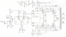
The phase splitter used in the K4040 is often referred to as concertina phase splitter, when looking at the schematic diagram it resembles a cathodyne phase splitter. One output at the annode, one at the cathode. With this setup there are problems like low gain, linearity and load sensibility.
I used a Schmidt phase splitter, the modification is a added 4mA constant current source. The Schmidt phase splitter is very linear, easy to adjust, stable and has low distortion. The outputs of the Schmidt phase splitter are both on the annodes, the constant current source lowers distortion.
I added a schematic diagram of the modifications I made, this makes it a bit clearer, the same reference numbers were used where possible, but I may have missed one, only the left channel is shown. The following list gives a overview of the modifications made:
1) 100nF/63V capacitor across D23, this will suppress hum on the bias readout.
2) R5 and R10 lowered to 10K, C29,31 increased to 100uF/100V, 47V zenerdiode across C29 and C31 (cathode to plus), this will stabilize the bias voltage, regardless of transformer load.
3) High-quality potentiometers for bias adjustment (Bourns or Spectrol)
4) V11 changed to ECC83, improved sound quality (ECC83 from phase splitter can be used)
5) R61=100k, R62=100K, R59=27k, R60=27K, R11=6K8, R16=6K8, this will set the correct gain for V11.
6) C5=100nF/1KV, C9=100nF/1KV polypropylene (Farnell P/N 106367)
7) Cathodyne phase splitter replaced by modified Schmidt phasesplitter (see diagram). J508 and J509 are 2mA constant current sources (Farnell P/N 9549951). V9 changed to ECC81 (RS P/N 5011342).
8) C11...14, C19...22 changed to 100nF/1KV polypropylene (Farnell P/N 106367)
9) RV1...4, RV5...8 changed to Bourns or Spectrol.
10) R89...96 changed to 1K Ohm 1W.
11) R32...34, R51, R29...31 and R38 changed to 1.5 K Ohm.
12) Overall feedback removed, only using local feedback.
13) Svetlana EL34's replaced by JJ KT77, clearer sound, better bass and trebles.
14) 3.3nF/5KV capacitors were placed in parallell with D11...D14 to suppress switch noise.
15) ZD1=3.9V zener instead of 7V5 (solves mains brownout problem, this is already modified in new kits)
The EL34 sockets may cause bad connections when a tube with bigger pin diameter has been inserted once, due to bent contacts, pin 5 should be checked carefully as it is also used to set the bias current. Higher quality tube sockets could be used.
All carbon film resistors were replaced with Beyschlag 1% metal film resistors for stability and lower noise.
Always be carefull working on high-voltage circuits, wait until the electrolytic capacitors are fully discharged. When modifications are made, always double check before switching-on the power.
Finishing touch, the chrome decorative rings may scratch the large chrome plate, so I applied protective self adhesive polycarbonate sheet (used to protect front panels) to avoid scratches.
Hi Alexiss,
Thanks for your reply [post #1033]
The phase splitter used in the K4040 is often referred to as concertina phase splitter, when looking at the schematic diagram it resembles a cathodyne phase splitter. One output at the annode, one at the cathode. With this setup there are problems like low gain, linearity and load sensibility.
I used a Schmidt phase splitter, the modification is a added 4mA constant current source. The Schmidt phase splitter is very linear, easy to adjust, stable and has low distortion. The outputs of the Schmidt phase splitter are both on the annodes, the constant current source lowers distortion.
I added a schematic diagram of the modifications I made, this makes it a bit clearer, the same reference numbers were used where possible, but I may have missed one, only the left channel is shown. The following list gives a overview of the modifications made:
1) 100nF/63V capacitor across D23, this will suppress hum on the bias readout.
2) R5 and R10 lowered to 10K, C29,31 increased to 100uF/100V, 47V zenerdiode across C29 and C31 (cathode to plus), this will stabilize the bias voltage, regardless of transformer load.
3) High-quality potentiometers for bias adjustment (Bourns or Spectrol)
4) V11 changed to ECC83, improved sound quality (ECC83 from phase splitter can be used)
5) R61=100k, R62=100K, R59=27k, R60=27K, R11=6K8, R16=6K8, this will set the correct gain for V11.
6) C5=100nF/1KV, C9=100nF/1KV polypropylene (Farnell P/N 106367)
7) Cathodyne phase splitter replaced by modified Schmidt phasesplitter (see diagram). J508 and J509 are 2mA constant current sources (Farnell P/N 9549951). V9 changed to ECC81 (RS P/N 5011342).
8) C11...14, C19...22 changed to 100nF/1KV polypropylene (Farnell P/N 106367)
9) RV1...4, RV5...8 changed to Bourns or Spectrol.
10) R89...96 changed to 1K Ohm 1W.
11) R32...34, R51, R29...31 and R38 changed to 1.5 K Ohm.
12) Overall feedback removed, only using local feedback.
13) Svetlana EL34's replaced by JJ KT77, clearer sound, better bass and trebles.
14) 3.3nF/5KV capacitors were placed in parallell with D11...D14 to suppress switch noise.
15) ZD1=3.9V zener instead of 7V5 (solves mains brownout problem, this is already modified in new kits)
The EL34 sockets may cause bad connections when a tube with bigger pin diameter has been inserted once, due to bent contacts, pin 5 should be checked carefully as it is also used to set the bias current. Higher quality tube sockets could be used.
All carbon film resistors were replaced with Beyschlag 1% metal film resistors for stability and lower noise.
Always be carefull working on high-voltage circuits, wait until the electrolytic capacitors are fully discharged. When modifications are made, always double check before switching-on the power.
Finishing touch, the chrome decorative rings may scratch the large chrome plate, so I applied protective self adhesive polycarbonate sheet (used to protect front panels) to avoid scratches.
Attachments
Hi MGH,
Thanks for your reply [post #1036]
No, of course I am not abandoning the octal D-I DAC , the PCB's will be ordered soon. The 16 X TDA1543 D-I DAC is a separate project.
The chassis I used for the octal D-I DAC had to match my audio set, that's why it's rather complicated. It basically consists of aluminum sheets and bars, some parts can be easily made by hand, using standard tools. The massive 8mm side panels have to be CNC machined. I have a look if the octal D-I DAC housing can be made cheaper, using less parts.
Thanks for your reply [post #1036]
No, of course I am not abandoning the octal D-I DAC
, the PCB's will be ordered soon. The 16 X TDA1543 D-I DAC is a separate project.The chassis I used for the octal D-I DAC had to match my audio set, that's why it's rather complicated. It basically consists of aluminum sheets and bars, some parts can be easily made by hand, using standard tools. The massive 8mm side panels have to be CNC machined. I have a look if the octal D-I DAC housing can be made cheaper, using less parts.
Hi John,
I'm glad you will do the TDA1543DAC.
If you go for the single PCB (timing chain + DAC + opamps) I'm affraid I would have to make my own PCB's for the DAC section,
because I plan to build a 1543 DI-DAC, à la Doede, and I will need some space around the chip's tower to put heatsinking
I'm with Doede, try the no-opamp version
Forza!
M
- Home
- Source & Line
- Digital Line Level
- Building the ultimate NOS DAC using TDA1541A