

Some more photographs...
Hi maxlorenz,
Thanks for your reply [post#981]
Looks like it's time to get the PCB's manufactured. I will post some more photographs of the octal D-I DAC, since I have made some more modifications to the housing.
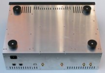
The first photograph shows the location of various ventilation slots. I have to add some more in the top cover.
Hi maxlorenz,
Thanks for your reply [post#981]
Looks like it's time to get the PCB's manufactured. I will post some more photographs of the octal D-I DAC, since I have made some more modifications to the housing.
The first photograph shows the location of various ventilation slots. I have to add some more in the top cover.
Attachments
Hi all,
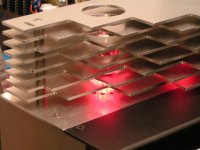
Another photograph, it shows the modified tube grille, the hexagonal spacers have been replaced by round precision turned aluminum spacers. More ventilation slots are added around the tube sockets and above the OPA627 OP-amps (these are located below the center of the tube cover plate). The slot on the top left is added to enable easy access to the cover's front screws. I also used countersunk screws on the top grille plate.
Another photograph, it shows the modified tube grille, the hexagonal spacers have been replaced by round precision turned aluminum spacers. More ventilation slots are added around the tube sockets and above the OPA627 OP-amps (these are located below the center of the tube cover plate). The slot on the top left is added to enable easy access to the cover's front screws. I also used countersunk screws on the top grille plate.
Attachments
hi all,
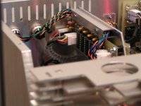
Another picture showing the completed wiring of both I2S inputs. I used colour coded twisted pairs for this. Blue/black = BCK, orange/black = WS, green/black = DATA. The cables are routed trough a small aluminum cover. The connectors used are 6-way DIN connectors with a screw locking mechanism. Both connector and socket are made of aluminum with a mat-chrome finish, the terminals are gold plated of course.
Another picture showing the completed wiring of both I2S inputs. I used colour coded twisted pairs for this. Blue/black = BCK, orange/black = WS, green/black = DATA. The cables are routed trough a small aluminum cover. The connectors used are 6-way DIN connectors with a screw locking mechanism. Both connector and socket are made of aluminum with a mat-chrome finish, the terminals are gold plated of course.
Attachments
Hi all,
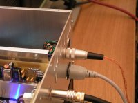
Next photograph shows the I2S DIN connector and the twisted pair stranded wire I2S interlink. The RCA connectors have a clamping mechanism, the RCA interlink cables are approx. 40cm long. The DAC RCA sockets are mounted on transparent 3mm polycarbonate plates to isolate them from frame ground.
Next photograph shows the I2S DIN connector and the twisted pair stranded wire I2S interlink. The RCA connectors have a clamping mechanism, the RCA interlink cables are approx. 40cm long. The DAC RCA sockets are mounted on transparent 3mm polycarbonate plates to isolate them from frame ground.
Attachments
How much does this DAC cost to make? Do you need any expensive testing equipment like an oscillator to make it? I just have a soldering iron, a multimeter, and a breadboard. I've made a few simple circuits before from other peoples' plans.
What are some other good DAC's that there are plans or kits available for? Is this the best one? I heard Benchmark DAC is THE one to buy, but $1,000 for a DAC is so much money.
What are some other good DAC's that there are plans or kits available for? Is this the best one? I heard Benchmark DAC is THE one to buy, but $1,000 for a DAC is so much money.
Quickness, looks like you're new to this thread. We have all been waiting patiently for months for the finalized product. EC has worked very hard on this design. I suggest you read the thread to see if it's doable for you. As for your questions on other DACs, this is probably not the appropriate thread to raise your questions. Try starting your own thread or search the forum. As for what is the BEST, that's really question with no right answer - depends on your taste, price range, skills as a DIYer, etc.
Project update
Hi all,
Project update.
I started checking and updating the PCB designs in order to prepare them for PCB manufacturing.
The DAC modules will be slightly modified to enable the use of 1...3.3uF film decoupling capacitors for MSB. I am also checking if I can prepare the PCB to enable the use of both the programmable upc1039 shunt regulators and the 78XX series regulators.
The analog mainboard will be modified to integrate the HC / HCT UHS BCK buffers in SOT23-5 package, so the small BCK buffer module is no longer necessary.
The I2S input switch module had a small error (WS inverted on channel 2) due to a incorrectly placed label in the schematic diagram, this has been corrected.
The USB to I2S interface seems to work slightly better when selecting 48KHz sample-rate on the mac.
I am also checking the possibility to add a small bypassable digital FIR filter in the timing-chain module. The idea is to use just enough oversampling (2X) to move the first mirror image out of the way, greatly reducing intermodulation effects, the FIR filter is always followed by the 8 times D-I interpolation. I already made a test setup using the CS8421 (asynchronous sample-rate converter), but it seems to be partially damaged as the digital filter outputs a lot of digital noise on the serial data output when enabled, even when the I2S data input is tied to GND. I ordered a new chip and will test it again next week, in order to find out what is causing this problem.
Some tests were done to see if the slight high-frequency rolloff in NOS / D-I mode could be compensated. By adding a few RC bypass networks on the attenuator, the drop in high frequency energy can be compensated this way.
Then there was a question from Quickne$$ about tools and test equipment needed. First of all, you need a good soldering iron, preferably with different tip sizes, after trying many brands I settled for Weller soldering stations with digital tip temperature readout. Then you need a digital multimeter, I use Fluke multimeters, the 9V battery lasts for ages and the meters are virtually indestructible. A oscilloscope would be usefull to check the operation of the assembled modules, but not strictly necessary. I use a Hameg oscilloscope, there is a new low cost 2 X 35 MHz version available now.
The modular setup of the octal D-I DAC, the use of IC sockets and connectors makes troubleshooting a lot easier. The circuits used are not critical, when assembled correctly they should work straight away. The only 2 adjustments are the DC settings for the tube amplifier, these can be checked with a multimeter. All I can say is when you take your time during assembly and double-check everything, there is no reason why the octal D-I DAC wouldn't work. Special care has to be taken to make sure the polarity of all electrolytic capacitors is correct. I also plan to provide detailed step by step assembly instructions, with lot's of photographs for reference.

Anyone else have anything to say regarding software resampling?
My impression was that it was to be avoided in general not only because it used a lot of CPU, but also because the results were often less than satisfactory, especially when compared to hardware resampling.
What sort of resampling algorithm does the Mac use? PPHS? SSRC? LI?
Also, I would like to reiterate my opinion that the RC bypass networks on the attenuator should be made bypassable - if HF rolloff is a problem inherent with NOS-DI circuits, I am hesitant about the wisdom of making and adding further error to correct for error.
Hi adhoc,
Thanks for your reply [post#991]
The mac I am using does both, decompressing the lossless compressed audio data stored on harddisk and resampling it on the fly, all it needs is about 5...10% of processor capacity. I am currently using a iMac with 500MHz G3 processor and USB1.0 running on OSX Panther. The sampling rate can be toggled in software (midi setting menu) between 32, 44.1 and 48KHz. I am not sure what type of resampling is used. After installing the new Itunes 7 version, 32KHz sample rate doesn't seem to work anymore.
I removed the RC correction circuit from the output attenuator in order to keep the signal as clean as possible.
Hi MGH,
Thanks for your reply [post992]
As you may have guessed, I have been very busy lately.
- The TDA1541A DAC module PCB design is modified in order to use 1...3.3uF capacitors for MSB decoupling. There is enough room to mount a standard 24pin size heatsink on the TDA1541A.
- The analog mainboard PCB design is modified so now it includes the 3 BCK (UHS) buffers.
- The main power supply PCB design is modified, it now directly feeds the system controller (5V) and a modification is made to switch-off the tube status LED's if desired.
I also spend a lot of time checking the layouts, especially drill diameters and silkscreen. If all this is completed, the PCB's can be manufactured.
The FIR filter (part of the CS8421 sample rate converter) worked, but it generated a lot of noise and massive low level distortion. Even when testing a second chip I got the same results. It isn't likely both chips are malfunctioning. The CS8421 has a automatic dithering circuit, but this shouldn't generate such high noise levels. It could be decimation noise, but I also get the same noise levels with 1:1 sample rate. So it seems the CS8421 unusable for this application.
So for now, I leave the octal D-I DAC design as it is. I am still experimenting with different component values and types to get even better results. I am also going to try Riken-ohm and tantalium resistors, especially in the I/V stages, tube output and attenuators.
When all component values are optimal, I can start making partlists for each module.
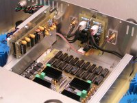
I added a photograph showing the green 3.3uF capacitors for decoupling MSB, the 24 pin size heatsinks and the high-capacity tantalium power supply decoupling cap's used in the USB interface.
Thanks for your reply [post992]
As you may have guessed, I have been very busy lately.
- The TDA1541A DAC module PCB design is modified in order to use 1...3.3uF capacitors for MSB decoupling. There is enough room to mount a standard 24pin size heatsink on the TDA1541A.
- The analog mainboard PCB design is modified so now it includes the 3 BCK (UHS) buffers.
- The main power supply PCB design is modified, it now directly feeds the system controller (5V) and a modification is made to switch-off the tube status LED's if desired.
I also spend a lot of time checking the layouts, especially drill diameters and silkscreen. If all this is completed, the PCB's can be manufactured.
The FIR filter (part of the CS8421 sample rate converter) worked, but it generated a lot of noise and massive low level distortion. Even when testing a second chip I got the same results. It isn't likely both chips are malfunctioning. The CS8421 has a automatic dithering circuit, but this shouldn't generate such high noise levels. It could be decimation noise, but I also get the same noise levels with 1:1 sample rate. So it seems the CS8421 unusable for this application.
So for now, I leave the octal D-I DAC design as it is. I am still experimenting with different component values and types to get even better results. I am also going to try Riken-ohm and tantalium resistors, especially in the I/V stages, tube output and attenuators.
When all component values are optimal, I can start making partlists for each module.
I added a photograph showing the green 3.3uF capacitors for decoupling MSB, the 24 pin size heatsinks and the high-capacity tantalium power supply decoupling cap's used in the USB interface.
Attachments
octal D-I DAC with passive I/V
Hi MGH,
Thanks for your reply [post#995-996]
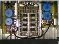
First of all the decoupling cap's were all increased in value on the majority of modules. I added a picture of this modification. The sound is very smooth now, the transparancy and low level detail have improved, noise levels have gone down too. This could be tested with a track containing a low level sinewave, slowly dissapearing in the noise floor.
But there is much more to come,
The op-amp I/V converters use 4 expensive OPA627's, so I decided to try passive I/V setups using non-inductive 15 Ohm copper wire resistors. Dual resistors were "merged" in a single winding because I use a differential setup. Then I increased the gain of the existing differential amplifiers. The enhancement in perceived sound quality was much more than I had expected.
I also tested both metal film and carbon resistors but they didn't even come close to the copper wire resistor. The copper wire resistor has zero inductance due to a twisted-pair mobius loop construction, the copper wire is much thicker than the metal or carbon film, this ensures very low noise.
I will post differential passive I/V schematic diagrams and copper wire resistor construction method's later.
Hi MGH,
Thanks for your reply [post#995-996]
First of all the decoupling cap's were all increased in value on the majority of modules. I added a picture of this modification. The sound is very smooth now, the transparancy and low level detail have improved, noise levels have gone down too. This could be tested with a track containing a low level sinewave, slowly dissapearing in the noise floor.
But there is much more to come,
The op-amp I/V converters use 4 expensive OPA627's, so I decided to try passive I/V setups using non-inductive 15 Ohm copper wire resistors. Dual resistors were "merged" in a single winding because I use a differential setup. Then I increased the gain of the existing differential amplifiers. The enhancement in perceived sound quality was much more than I had expected.
I also tested both metal film and carbon resistors but they didn't even come close to the copper wire resistor. The copper wire resistor has zero inductance due to a twisted-pair mobius loop construction, the copper wire is much thicker than the metal or carbon film, this ensures very low noise.
I will post differential passive I/V schematic diagrams and copper wire resistor construction method's later.
Attachments
Hello ecdesigns,
did you considered the possibility of using fully balanced opamps from Texas instruments ( SuSy (tm) ) ?
I had experiece with susy (tm) circuits and can say they are fantastic sounding amps .
Morover , that way , you would just need 1 opamp par channel with a true supersymmetric balanced output before the tube stage .
DEM
Hi,
From reading the papers on tda1541a internals http://www.diyaudio.com/forums/showthread.php?postid=1017552#post1017552 I understand DEM fs to be independent of sample fs. If you derive the DEM clock from the sample rate doesn't this mean you introduce 'jitter' errors into the current sources. The paper refers to the timing accuracy of the interchanging network which I assume means jitter. Maybe I have mis-understood the papers.
- Home
- Source & Line
- Digital Line Level
- Building the ultimate NOS DAC using TDA1541A