8 X TDA1541 or 16...64 X TDA1543?
Hi tubee,
Thanks for your reply [post#594]
I got the TDA1543's from NEDIS, they will receive new ones soon. Yes I already start worrying, with the AD823 I/V stage and the OPA627 diff amp, the 16 X TDA1543 DAC is catching up fast with the octal D-I DAC. It already has that smooth crystal clear open sound that even seems to improve the longer the DAC is switched on. I was worried that the linear interpolation with 16 DAC's would cause a disturbing high frequency rolloff, but it seems to work beyond expectation. The added even harmonic distortion produced with this setup (linear interpolation), starts to resemble the mixed mode on the octal D-I DAC, and brings a beautiful balance to sound quality.
TDA1543 setup
Hi maxlorenz,
Thanks for your reply [post#595]
Yes, Dutchman also listened to the octal TDA1543 D-I DAC setup and the smaller semi-3 way sonic resonators in the cellar. (my cellar hasn't got the best acoustics). But that was Saturday, Sunday the setup already evolved to a 16 DAC version as can be seen on the photograph [post#589]. Today the OPA2132 (I/V stage) was replaced by a AD823. And I wouldn't be John if I didn't try both the 32 and 64 DAC D-I setup as soon as I got time. I am also working on the octal D-I DAC housing. Sidepanels, bottom plate and top cover are already machined. Now I can start to figure out where to place the power supplies, system controller, I2S input selector and the analog switching module.
TDA154?
Hi MGH,
Thanks for your reply [post#596]
Yes, good question. At the moment the TDA1541A octal D-I DAC sounds better, but as I already noted, the 16 X TDA1543 D-I version is catching up fast. I am already very curious how a 32 or 64 TDA1543 D-I version would compare to it.
Hi MGH,
Thanks for your reply [post#596]
Yes, good question. At the moment the TDA1541A octal D-I DAC sounds better, but as I already noted, the 16 X TDA1543 D-I version is catching up fast. I am already very curious how a 32 or 64 TDA1543 D-I version would compare to it.
Hi ecdesigns,
Man, I wish you lived next door!
(and we could compare your sonic resonators to my DIY Tannoy Autograph's enclosures )
Keep the good work.
M
Today the OPA2132 (I/V stage) was replaced by a AD823. And I wouldn't be John if I didn't try both the 32 and 64 DAC D-I setup as soon as I got time.
Man, I wish you lived next door!
(and we could compare your sonic resonators to my DIY Tannoy Autograph's enclosures
)Keep the good work.
M
Hi ErikdeBest,
Dutchmen are so laconic! 
I know how multi 1543 can sound. Please comment about high frequency's performance of this DAC
Gratefully yours,
M
Last Friday I visited ec-designs, curious about his system. I liked it a lot. I also heard the 8x TDA1543 version, but this was on another system, another room. But sure, not bad either!
Dutchmen are so laconic!
I know how multi 1543 can sound. Please comment about high frequency's performance of this DAC
Gratefully yours,
M
Octal D-I DAC housing
Hi all,
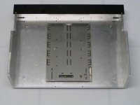
After all the electronics, something completely different, the octal D-I DAC housing.
I will post some more pictures of the octal D-I DAC housing later. This is the first one, it shows the massive 8mm thick aluminum sidepanels, the bottom plate and the keyboard / indicator frame. At the center, the analog mainboard with a thin aluminum screen plate already fitted. It is placed between both the analog mainboard and the modules. On top of the screen plate is a thin polyester foil for insulation. The 4 round feet are made of acetal copolymer, with a embedded 3mm thick neoprene rubber disc to avoid scrathes.
All parts, polyester foil included were manufactured using a CNC milling machine.
Hi all,
After all the electronics, something completely different, the octal D-I DAC housing.
I will post some more pictures of the octal D-I DAC housing later. This is the first one, it shows the massive 8mm thick aluminum sidepanels, the bottom plate and the keyboard / indicator frame. At the center, the analog mainboard with a thin aluminum screen plate already fitted. It is placed between both the analog mainboard and the modules. On top of the screen plate is a thin polyester foil for insulation. The 4 round feet are made of acetal copolymer, with a embedded 3mm thick neoprene rubber disc to avoid scrathes.
All parts, polyester foil included were manufactured using a CNC milling machine.
Attachments
Hi all,
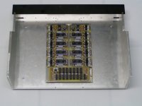
Picture 2 of the octal D-I DAC housing.
Here the modules have been placed, as indicated, a thin polyester foil will prevent possible short circuits. The screen plate is used for addittional interference reduction. The massive aluminum side pannels are the base of the entire housing, all plates are attached to them using M3 screws. The M3 thread is tapped into the aluminum sidepanels. The aluminum parts are annodized later for a professional finish.
Attachments

Hi all,
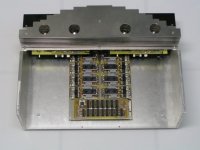
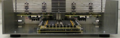
Picture 3 of the octal D-I DAC housing.
The tube output frame is put into position, special care had to be taken to ensure there was enough clearance between both the analog mainboard and the tube output stage circuit boards. Also the I/V stage outputs had to be located close to the tube output stage, to avoid hum. The entire tube output module can be taken out, by just removing 4 M3 screws, and pulling some connectors. The grid plates are mounted using 5mm spacers. The entire grid can be taken off by removing 3 screws. The tubes can be changed either with a special tube pulling tool (similar to the tools used to remove pilot lamps from switches), or by removing the protective grid first. Power supplies will be placed on two sub-chassis, both left and right from the analog mainboard.
Attachments
Hi all,
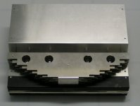
Picture 4 of the octal D-I DAC housing.
A front view, notice the sloped cover, I had to bend it myself. All screws will be hexagonal countersunk types. I am planning to annodize the entire housing black, exept for the protective grid. The grid will be annodized natural (aluminum color), so it stand's out. Other colour combinations are possible though, perhaps annodized gold colour for the protective grid would look nice too. The shiny bar on the front panel is 5mm thick massive stainless steel, polished to high gloss.
Attachments
Opamps
John: as usual it looks very good, again and again!
In what way do you use the opamps? This i ask because after listening a while now to the modded some 304 with OP2132 opamps, made some conclusions.
After listening to(the very good sounding) 304 with 2132 opamp i recognised, but only with my self designed OTL tubed in triode ECC85/El95 headphone amp, a sort of settling-time with fast transients in music. Very subtle but i can hear it. Its like the opamp cannot keep up with the output signal for a very short time. I tried before a discrete I/V with 4 transistors on other cdp, rbroertjes I/V. This schematic uses a common base design, often used in HF circuits, so faster. At the moment i am allmost ready to try Rogics AD844 I/V on veroboard, this I/V is also common base design. Imo the common base implementation could be better compared to the standard opamp with a feedback loop in it.
So i am curious about the sound of Pedja's AD844 stage, especially its performing with fast transients.
http://www.pedjarogic.com/1541a/pdf/rev1_1b_sch.pdf
John: as usual it looks very good, again and again!
with the AD823 I/V stage and the OPA627 diff amp, the 16 X TDA1543 DAC is catching up fast with the octal D-I DAC
In what way do you use the opamps? This i ask because after listening a while now to the modded some 304 with OP2132 opamps, made some conclusions.
After listening to(the very good sounding) 304 with 2132 opamp i recognised, but only with my self designed OTL tubed in triode ECC85/El95 headphone amp, a sort of settling-time with fast transients in music. Very subtle but i can hear it. Its like the opamp cannot keep up with the output signal for a very short time. I tried before a discrete I/V with 4 transistors on other cdp, rbroertjes I/V. This schematic uses a common base design, often used in HF circuits, so faster. At the moment i am allmost ready to try Rogics AD844 I/V on veroboard, this I/V is also common base design. Imo the common base implementation could be better compared to the standard opamp with a feedback loop in it.
So i am curious about the sound of Pedja's AD844 stage, especially its performing with fast transients.
http://www.pedjarogic.com/1541a/pdf/rev1_1b_sch.pdf
Hi all,
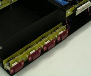
Picture 5 of the octal D-I DAC housing.
Rear view of the housing, now the position of both tube output modules and analog mainboard can be seen. The rectangular holes at the left and the right of the keyboard / indicator panel are used for routing wires. At the moment I use a combination of both a power metal film and a carbon resistor for the cathode follower resistors.
To answer NjoyTHEMUSIC's question, yes the 3 regulators located at each DAC chip are dedicated for that chip only. The 3 pin regulators have been selected for close tolerance. This technique is used troughout the entire octal D-I DAC design, each chip basically has it's own separate power supply. These supplies are thouroughly decoupled on the analog mainboard. So crosstalk between power supplies is very low. The regulators are also placed very close to the chip's.
Attachments
Hi tubee,
Thanks for your reply [post#611]
The I/V op-amp needs to be very fast (short settling time) the OPA2132 isn't fast enough for this particular application. So your conclusion is correct. Now I use a faster AD823 (Dual) that works much better. But as already noted, I saw another interesting OP-amp for I/V conversion on this site, the Linear Technology LT1469. So the op-amp specifications for the I/V stage differ considerably from the one used in the diff-amp. However, the OPA627 seems to work very well for I/V conversion too. But the LT1496 could proove to be a better choise. Discrete setups are sometimes less accurate (linearity) and have problems with stability (drift). I already tried some of them, but still prefer a high quality OP-amp.
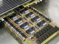
note that I currently use the OPA627 for I/V conversion in the octal D-I DAC and the AD823 in the 16 X TDA1543 D-I setup.
I added a close-up of the analog mainboard,
Thanks for your reply [post#611]
The I/V op-amp needs to be very fast (short settling time) the OPA2132 isn't fast enough for this particular application. So your conclusion is correct. Now I use a faster AD823 (Dual) that works much better. But as already noted, I saw another interesting OP-amp for I/V conversion on this site, the Linear Technology LT1469. So the op-amp specifications for the I/V stage differ considerably from the one used in the diff-amp. However, the OPA627 seems to work very well for I/V conversion too. But the LT1496 could proove to be a better choise. Discrete setups are sometimes less accurate (linearity) and have problems with stability (drift). I already tried some of them, but still prefer a high quality OP-amp.
note that I currently use the OPA627 for I/V conversion in the octal D-I DAC and the AD823 in the 16 X TDA1543 D-I setup.
I added a close-up of the analog mainboard,
Attachments
Keys
Hi all,
Next picture shows a close-up of the self made keys with backlit symbols. The rear PCB holds the actual short travel switches. They are mechanically connected to the CNC machined red transparent Plexiglass keys, using a polycarbonate frame, two aluminum spacers and countersunk M3 nylon screws . In between there is a second fixed PCB holding the LED blocks for backlighting. This way symbols can be perfectly illuminated trough the moving keys. Oh yes, the symbols are etched in a 1mm thick printed circuit board, the copper block's off the light, and the etched pattern becomes visible. The EC designs logo on the right is made in a similar way. I tinned it to prevent oxidation. The keys will fit in the rectangular holes of the front cover.
This setup will also be used for the octal D-I DAC, the system controller module will probably be mounted on this chassis as well. This way it's located in a Farraday's cage to avoid interference from the microcontroller.
Attachments
opamps 2
Yes John agreed, the discrete i/v has some coloration or so, i cannot discribe. Also it emphasises continous tones, the 2132 opamps emphasises "rhytms" and subtle details, i like it more then the discrete i/v.
Oh and i will ask a friend of my, if he wants to join me for the long journey to your residence, and we'll listen to your D-I dac and resonators! (if you don't mind) But he is a busy man too.
Discrete setups are sometimes less accurate (linearity) and have problems with stability (drift)
Yes John agreed, the discrete i/v has some coloration or so, i cannot discribe. Also it emphasises continous tones, the 2132 opamps emphasises "rhytms" and subtle details, i like it more then the discrete i/v.
Oh and i will ask a friend of my, if he wants to join me for the long journey to your residence, and we'll listen to your D-I dac and resonators! (if you don't mind) But he is a busy man too.
TDA1543 octal D-I DAC schematics
Hi tubee,
Thanks for your reply [post#616]
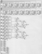
Well I used the OP-amps this way (see added schematic diagram). It's a rough setup for a single board octal D-I DAC using the TDA1543. The timing chain has plenty of taps to build a 16, 32 or 64 D-I DAC using the TDA1543. The setup is balanced / DC coupled since output capacitors are too expensive . Decoupling cap's can be added between each AD823 NON-inverting input (reference) and ground.
Enjoy.
Hi tubee,
Thanks for your reply [post#616]
Well I used the OP-amps this way (see added schematic diagram). It's a rough setup for a single board octal D-I DAC using the TDA1543. The timing chain has plenty of taps to build a 16, 32 or 64 D-I DAC using the TDA1543. The setup is balanced / DC coupled since output capacitors are too expensive
. Decoupling cap's can be added between each AD823 NON-inverting input (reference) and ground.Enjoy.
Attachments
- Home
- Source & Line
- Digital Line Level
- Building the ultimate NOS DAC using TDA1541A