Hi JOSI1,
Every (relay) contact in the signal path reduces performance, especially low level performance (check relay contact low voltage specs). So it is best to have fewest of these contacts in the signal path. For this reason we reduced the amount of relays to 5 and removed the input selector. So this is a step forward as we increased (low level) performance.
Yes, with this application I need low noise, low stray inductance and low stray capacitance. The thin film 805 size NiCr SMD resistors provide all this.
when looking at the picture of the Relay Volume Control Module in Post #5747
it seems you changed to a serial volume control with up to 5 Relay contacts / SMD resistors in the signal path. Isn't this a step back compared to shunt volume control you used in the past.
Every (relay) contact in the signal path reduces performance, especially low level performance (check relay contact low voltage specs). So it is best to have fewest of these contacts in the signal path. For this reason we reduced the amount of relays to 5 and removed the input selector. So this is a step forward as we increased (low level) performance.
Is the use of thin film low noise precision resistors even the better choice (compact size, no lead wires, low stray inductance and capacitance) for a relay volume control.
Are ni-chrome resistors suited best?
Yes, with this application I need low noise, low stray inductance and low stray capacitance. The thin film 805 size NiCr SMD resistors provide all this.
Nice screen. The problem is that Chinese re-sellers won't support you. For example, no one answered what the magnitude Vout for the I2S signals is?. If it is less than 1,2V, chances are that our beloved TDA1543 doesn't get exited, and if it is less than 1,5V maybe "I2S attenuator circuit" won't work.
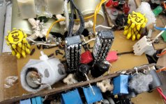
IF I2S were higher, the player could be used with DUAL-MONO DAC. I attach some pictures of my DUAL-MONO in 4x2 version: two towers of 4 chips. Best midbass ever...
One of -EC- Vregs is visible on top.
Cheers,
M.
Nice TDA1543 stacking Max. Mid-bass bliss.
With the Chinese SD card player with no manual; I think its more fun when the Chinese cant give support. More DIY adventure.
How can I measure the I2S output voltage magnitude? I only have a multimeter. Do I need to buy a digital oscilloscope?
Hi mr_whocares,
Nowadays audiophiles prefer audio streaming and an USB interface. So this Laminar transport may already be outdated before it is introduced.
I can understand the high price as I have been running my own company since 1990 and know how these prices have been calculated. Also consider that 192/24 playback using a SD-card requires the 4 bit parallel interface and then one has to pay high annual fees to the SD-card association. In order to use long file names one has to pay licence fees to Microsoft. These fees have to be included in the product price as well.
The 32GB limit is strange, we had no problems supporting 32GB cards and higher (theoretically up to 2 TB) on our latest SD-player.
Clean digital audio source only makes sense when the clean signals generated by it stay clean all the way up to the D/A converter. That's why I integrated both, SD-transport and DAC. When using an external DAC, connected through S/PDIF, AES/EBU, or I2S I have serious doubts if clean interface signals can be maintained all the way up to the D/A converter.
Based on this I would expect only marginal improvements or just a slightly -different- sound.
In order to read SD-cards, play files up to 192/24 and access the file system one needs certain hardware and software. Small computers like the RaspBerry Pie 3 for example offer very similar performance. So why re-invent the wheel and not simply use available, extensively tested and debugged hardware and software?
Lessloss uses a processor clock that's an exact multiple of the sample rate. This would be problematic when using the RaspBerry Pie.
Other problem is the user interface, the tiny LC display on the streamer is far from ideal.
Apart from all this, there are major problems with conventional digital audio. We want involving music instead of just artificial sound. We already -had- involving music when using vinyl and tape, long before digital audio was introduced.
Conventional DACs still sound artificial and over a decade of world wide research hasn't fixed this issue yet.
One can design the most fantastic digital audio sources with superb technical specs and put these in very impressive enclosures. But when all this doesn't produce involving music its a failed mission.
the lessloss sd player seems finally to be for sale at 90k euro and they claim to be the world first of its kind , handling up to 32gb sd cards...
.... oh... world first? hmmm.... my 5 years old EC-design sd player works very fine with my old 64gb sd cards ;-)
Laminar Streamer SD player : High end SD player | Solid state memory player | Computer audio player
Nowadays audiophiles prefer audio streaming and an USB interface. So this Laminar transport may already be outdated before it is introduced.
I can understand the high price as I have been running my own company since 1990 and know how these prices have been calculated. Also consider that 192/24 playback using a SD-card requires the 4 bit parallel interface and then one has to pay high annual fees to the SD-card association. In order to use long file names one has to pay licence fees to Microsoft. These fees have to be included in the product price as well.
The 32GB limit is strange, we had no problems supporting 32GB cards and higher (theoretically up to 2 TB) on our latest SD-player.
Clean digital audio source only makes sense when the clean signals generated by it stay clean all the way up to the D/A converter. That's why I integrated both, SD-transport and DAC. When using an external DAC, connected through S/PDIF, AES/EBU, or I2S I have serious doubts if clean interface signals can be maintained all the way up to the D/A converter.
Based on this I would expect only marginal improvements or just a slightly -different- sound.
In order to read SD-cards, play files up to 192/24 and access the file system one needs certain hardware and software. Small computers like the RaspBerry Pie 3 for example offer very similar performance. So why re-invent the wheel and not simply use available, extensively tested and debugged hardware and software?
Lessloss uses a processor clock that's an exact multiple of the sample rate. This would be problematic when using the RaspBerry Pie.
Other problem is the user interface, the tiny LC display on the streamer is far from ideal.
Apart from all this, there are major problems with conventional digital audio. We want involving music instead of just artificial sound. We already -had- involving music when using vinyl and tape, long before digital audio was introduced.
Conventional DACs still sound artificial and over a decade of world wide research hasn't fixed this issue yet.
One can design the most fantastic digital audio sources with superb technical specs and put these in very impressive enclosures. But when all this doesn't produce involving music its a failed mission.
Hi Kazap,
Play music and measure the average DC voltage on WS, multiply it by two and you have a rough indication of the peak to peak voltage. Then take most logical peak to peak voltage (usually 5Vpp or 3V3pp)
Measured average DC voltage of 2V5 would indicate 5Vpp, average DC voltage of 1V65 would indicate 3Vpp. This is based on the assumption that WS is a symmetrical square wave.
You may have to leave out the I2S attenuators or modify these so they work correctly with the signal amplitude. Using series resistors (max. 1K) also helps to attenuate unwanted harmonics.
I2S is a -very- problematic interface due to its high power spectrum (harmonics) being generated by it when streaming audio. For this reason I gave up on I2S and developed the multi-stream digital audio interface.
It offers less than 1% of the interference energy compared to I2S without using any attenuators. This has two reasons, first I use multiple parallel streams so data can be loaded into the D/A converter in a fraction of the time required by I2S, the interface can be shut down (zero interference) during the rest of the sample period time.
Second I use very narrow pulse operation instead of using symmetrical square waves. This greatly reduces interface interference energy levels and balances the spectrum as even order harmonics are also generated this way. Symetrical square waves mainly generate odd order harmonics and this is one of the reasons it is almost impossible to get music out of digital audio.
But this requires a D/A converter that has a native multi-stream interface.
For TDA1541A we can use the simultaneous interface in order to reduce interface interference power levels. I would advise to run the TDA1541A in simultaneous mode whenever possible, the resulting sound quality is an improvement over I2S.
TDA1543 has no simultaneous interface, however we can simulate a simultaneous interface by using only one channel of the TDA1543 so we need two chips for stereo. It is still possible to stack multiple TDA1543 chips for higher full-scale current and lower I/V resistor impedance (and related output impedance) when using passive I/V conversion.
TDA1541A, simultaneous:
DATA-L, data for left channel
DATA-R, data for right channel
CLK, clock signal
LE, Latch signal (determines sample timing).
L+R data is clocked in simultaneously using BCK (requires 16 pulses). After the circuits have settled (zero ground-bounce) a LE pulse is applied to latch both outputs. The simultaneous interface is inactive during 75% of a 64 BCK frame.
Dual TDA1543, quasi simultaneous mode:
Chip #1,
DATA-L, 16 bits are clocked in when WS is high, only R channel can be used, it will receive data for the left audio channel
BCK, clock signal, used to clock in 16 bits and generate the LE signal after WS has gone low and the circuits have settled (zero ground-bounce).
WS, selects the channel and informs the chip when to look for the single latching pulse on BCK.
Chip #2,
DATA-R, 16 bits are clocked in when WS is high, only R channel can be used, it will receive data for the right audio channel
BCK, clock signal, used to clock in 16 bits and generate the LE signal after WS has gone low and the circuits have settled (zero ground-bounce).
WS, selects the channel and informs the chip when to look for the single latching pulse on BCK.
Left channel connects to the R output of chip #1, right channel connects to the R output of chip #2. This also enables perfect matching of both L and R channels.
The quasi simultaneous interface is inactive during 75% of a 64 bits frame.
How can I measure the I2S output voltage magnitude? I only have a multimeter. Do I need to buy a digital oscilloscope?
Play music and measure the average DC voltage on WS, multiply it by two and you have a rough indication of the peak to peak voltage. Then take most logical peak to peak voltage (usually 5Vpp or 3V3pp)
Measured average DC voltage of 2V5 would indicate 5Vpp, average DC voltage of 1V65 would indicate 3Vpp. This is based on the assumption that WS is a symmetrical square wave.
You may have to leave out the I2S attenuators or modify these so they work correctly with the signal amplitude. Using series resistors (max. 1K) also helps to attenuate unwanted harmonics.
I2S is a -very- problematic interface due to its high power spectrum (harmonics) being generated by it when streaming audio. For this reason I gave up on I2S and developed the multi-stream digital audio interface.
It offers less than 1% of the interference energy compared to I2S without using any attenuators. This has two reasons, first I use multiple parallel streams so data can be loaded into the D/A converter in a fraction of the time required by I2S, the interface can be shut down (zero interference) during the rest of the sample period time.
Second I use very narrow pulse operation instead of using symmetrical square waves. This greatly reduces interface interference energy levels and balances the spectrum as even order harmonics are also generated this way. Symetrical square waves mainly generate odd order harmonics and this is one of the reasons it is almost impossible to get music out of digital audio.
But this requires a D/A converter that has a native multi-stream interface.
For TDA1541A we can use the simultaneous interface in order to reduce interface interference power levels. I would advise to run the TDA1541A in simultaneous mode whenever possible, the resulting sound quality is an improvement over I2S.
TDA1543 has no simultaneous interface, however we can simulate a simultaneous interface by using only one channel of the TDA1543 so we need two chips for stereo. It is still possible to stack multiple TDA1543 chips for higher full-scale current and lower I/V resistor impedance (and related output impedance) when using passive I/V conversion.
TDA1541A, simultaneous:
DATA-L, data for left channel
DATA-R, data for right channel
CLK, clock signal
LE, Latch signal (determines sample timing).
L+R data is clocked in simultaneously using BCK (requires 16 pulses). After the circuits have settled (zero ground-bounce) a LE pulse is applied to latch both outputs. The simultaneous interface is inactive during 75% of a 64 BCK frame.
Dual TDA1543, quasi simultaneous mode:
Chip #1,
DATA-L, 16 bits are clocked in when WS is high, only R channel can be used, it will receive data for the left audio channel
BCK, clock signal, used to clock in 16 bits and generate the LE signal after WS has gone low and the circuits have settled (zero ground-bounce).
WS, selects the channel and informs the chip when to look for the single latching pulse on BCK.
Chip #2,
DATA-R, 16 bits are clocked in when WS is high, only R channel can be used, it will receive data for the right audio channel
BCK, clock signal, used to clock in 16 bits and generate the LE signal after WS has gone low and the circuits have settled (zero ground-bounce).
WS, selects the channel and informs the chip when to look for the single latching pulse on BCK.
Left channel connects to the R output of chip #1, right channel connects to the R output of chip #2. This also enables perfect matching of both L and R channels.
The quasi simultaneous interface is inactive during 75% of a 64 bits frame.
As always, -ECdesigns- is above and beyond our frame of reference 
While we wait for the "final" Mosaic DAC, can we mod the 1543 DUAL-MONO DAC to have the "quasi-simultaneous mode DAC you describe"?
Perhaps by disconnecting PIN6?
Exactly. It's all about satisfaction. That is why I continue to play with the obsolete and noisy 1543 It produces involving and entertaining music, not the cleanest but who cares...
Attached, a detail picture of my 8*2 DUAL-MONO-SDplayer, with 130 Ohm honeycomb resistors. I have to include a temperature controlled air cooling system and some sort of Faraday cage...
About USB, apart the several ADUM4160 based offers, check out this one:
6moons audioreviews: Intona High-Speed USB 2.0 Isolator
Thanks -EC-
M.
While we wait for the "final" Mosaic DAC, can we mod the 1543 DUAL-MONO DAC to have the "quasi-simultaneous mode DAC you describe"?
Perhaps by disconnecting PIN6?
Conventional DACs still sound artificial and over a decade of world wide research hasn't fixed this issue yet.
One can design the most fantastic digital audio sources with superb technical specs and put these in very impressive enclosures. But when all this doesn't produce involving music its a failed mission.
Exactly. It's all about satisfaction. That is why I continue to play with the obsolete and noisy 1543
It produces involving and entertaining music, not the cleanest but who cares...Attached, a detail picture of my 8*2 DUAL-MONO-SDplayer, with 130 Ohm honeycomb resistors. I have to include a temperature controlled air cooling system and some sort of Faraday cage...
About USB, apart the several ADUM4160 based offers, check out this one:
6moons audioreviews: Intona High-Speed USB 2.0 Isolator
Thanks -EC-
M.
Attachments
Hi Kazap,
Dual TDA1543, quasi simultaneous mode:
Chip #1,
DATA-L, 16 bits are clocked in when WS is high, only R channel can be used, it will receive data for the left audio channel
BCK, clock signal, used to clock in 16 bits and generate the LE signal after WS has gone low and the circuits have settled (zero ground-bounce).
WS, selects the channel and informs the chip when to look for the single latching pulse on BCK.
Chip #2,
DATA-R, 16 bits are clocked in when WS is high, only R channel can be used, it will receive data for the right audio channel
BCK, clock signal, used to clock in 16 bits and generate the LE signal after WS has gone low and the circuits have settled (zero ground-bounce).
WS, selects the channel and informs the chip when to look for the single latching pulse on BCK.
Left channel connects to the R output of chip #1, right channel connects to the R output of chip #2. This also enables perfect matching of both L and R channels.
The quasi simultaneous interface is inactive during 75% of a 64 bits frame.
Might there be a schematic available somewhere with this approach?
Thank you very much for any pointers.
Marco
Hi maxlorenz,
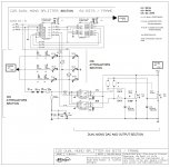
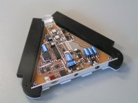
You will need an I2S to quasi simultaneous decoder circuit for that. I developed one based on a 16V8 PAL and some additional logic circuits. I used this circuit in the UD1 DAC (attached picture).
Problem here is that I2S already already did its damage and the quasi simultaneous interface passes it on to both TDA1543 chips. Therefore we need a (USB) audio receiver that outputs quasi multi-stream on it's I/O pins.
We plan to design and offer a DIY board next year, it will be based on our novel USB audio receiver chip and a TDA1541A or 2 x TDA1543 running in simultaneous vs quasi simultaneous mode.
I no longer use isolators, with the novel USB audio processor it's no longer required anyway. Isolators use and generate frequencies and harmonics that are added to the harmonics spectrum of the interface signal being isolated. This will always lead to significant and clearly audible degrading. With some isolators one can measure tremendous increase in noise level on the DAC output. This would be the case with isolators that run on internal oscillators.
While we wait for the "final" Mosaic DAC, can we mod the 1543 DUAL-MONO DAC to have the "quasi-simultaneous mode DAC you describe"?
Perhaps by disconnecting PIN6?
You will need an I2S to quasi simultaneous decoder circuit for that. I developed one based on a 16V8 PAL and some additional logic circuits. I used this circuit in the UD1 DAC (attached picture).
Problem here is that I2S already already did its damage and the quasi simultaneous interface passes it on to both TDA1543 chips. Therefore we need a (USB) audio receiver that outputs quasi multi-stream on it's I/O pins.
We plan to design and offer a DIY board next year, it will be based on our novel USB audio receiver chip and a TDA1541A or 2 x TDA1543 running in simultaneous vs quasi simultaneous mode.
About USB, apart the several ADUM4160 based offers, check out this one:
I no longer use isolators, with the novel USB audio processor it's no longer required anyway. Isolators use and generate frequencies and harmonics that are added to the harmonics spectrum of the interface signal being isolated. This will always lead to significant and clearly audible degrading. With some isolators one can measure tremendous increase in noise level on the DAC output. This would be the case with isolators that run on internal oscillators.
Attachments
Hi Max
If I may pls go look for a SDtrans 384 & power it
individually with low noise PS.
Promise you that it will be a Ear Opener
and thank you to Bunpei & Chiaki for creating
this wonderful device
Merry Xmas to all
Thanks. I followed that thread for a while, then quit, as I am fine with 16/44 files, for now.
Seem to be hard to find anyway.
To John,
I no longer use isolators, with the novel USB audio processor it's no longer required anyway.
Yes, I remember this feature indeed.
Eager to try it.I was addressing to the rest of USB DAC users that have the $ to spend.
Bet wishes for all,

M.
Happy holidays!
Thanks! Santa brought me a couple of big heat sinks today
Hi Max
Im also using it just for 16/44.1
Have a modded QLS like you too
but A/B wow SQ day & nite .
Out of the box it sounded just
as good as my 2 hi end Cdp
but after I added the PS,
different story. It ran away
from the pack. Also discovered
it outputs PCM which I will try
soon to connect to my AYA ll
Cheers & Merry Xmas
Computer audio really is crazy.
I decided to try an old MSI motherboard today. Fresh install of windows 7 x86, the mobo works right away with the standard drivers included in the OS. So I didn´t install any intel high performance drivers. Guess what? WAY better sound! A very surprising improvement. And I am using a toslink I/O and master clock at the DAC! Go figure.
(It´s just like John said: there is no zero bandwidth interface).
Hi maxlorenz,
We plan to design and offer a DIY board next year, it will be based on our novel USB audio receiver chip and a TDA1541A or 2 x TDA1543 running in simultaneous vs quasi simultaneous mode.
That would be great!

Can TDA1541A be ran in dual-mono configuration also?
Would it be worthy to add both DAC outputs, like the L/L and R/R chanels of the 1543 DUAL-MONO?
Cheers,
M.
I remember John had tried dual mono TDA1541A conf but had measured more jitter than with a standalone one (because of the variation in factory production, there are not exactly two identical chip... and I surmise also the variation with the 14 caps values to cause troubles between two TDA1541A as well) . It was towards the beginning of this thread iitc !
It's a good news john if you offer the possibility of a DIY DAC at DIY price with the TDA1541A as Pedja Rogic from Audial did with his AYA 2 since 2014.
Any chance to have your prefered I/V discrete stage on it ?
Thanks for that,

It's a good news john if you offer the possibility of a DIY DAC at DIY price with the TDA1541A as Pedja Rogic from Audial did with his AYA 2 since 2014.
Any chance to have your prefered I/V discrete stage on it ?
Thanks for that,
Last edited:
Iancanada's I2S-pcm board is already available for $79 and provides L/-L AND R/-R for dual differential simultaneous mode as well as for a single dac.That would be great!
Can TDA1541A be ran in dual-mono configuration also?
Would it be worthy to add both DAC outputs, like the L/L and R/R chanels of the 1543 DUAL-MONO?
Cheers,
M.
It has I2S inputs so you will need a receiver / decoder. I have one ready to install and its a professionally built pcb.
http://www.diyaudio.com/forums/grou...-pdif-fifo-kit-group-buy-188.html#post4357477
The best I/V seems to be the AD844 and if you use differential dac mode, the 1541'a 2ma offset can be ignored. An OPA627 can be used as differential to single ended buffer on the TZ pins.
Last edited:
Iancanada's I2S-pcm board is already available for $79 and provides L/-L AND R/-R for dual differential simultaneous mode as well as for a single dac.
It has I2S inputs so you will need a receiver / decoder. I have one ready to install and its a professionally built pcb.
http://www.diyaudio.com/forums/grou...-pdif-fifo-kit-group-buy-188.html#post4357477
The best I/V seems to be the AD844 and if you use differential dac mode, the 1541'a 2ma offset can be ignored. An OPA627 can be used as differential to single ended buffer on the TZ pins.
Thank you dear. Nice project.
But as I understand, you can't have I2S and simultaneous mode at the same time...
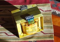
Anyway, look what Santa brought today...a 2,5KVA Balanced Power Transformer.
Guys, I will recommend again that you try this approach. It surely adds to the musical enjoyment. I am using now one main TX for the amp and one little TX in series for the SD player isolation. Get rid of reactive currents! (so they say)
Greetings,
M.
PS: dear John, don't forget to announce when the Mosaic is ready for purchase.

Attachments
I/V output stage
Well IMHO a discrete solution has potential of sounding better than any op-amp solution.
For the 1543, I have had the configuration maxlorenz uses, but I made another I/V stage that keeps the output from 1543 at almost 0 V.
To my ears this is better than the completely passive solution.
You are welcome to try it, but I keep commercial copyright to it.
I have PCB layout an silkscreen as well.
Attachments
- Home
- Source & Line
- Digital Line Level
- Building the ultimate NOS DAC using TDA1541A