Thanks John,
I need to read the IEEE docs some more.
In my mind your explanation seems to lead to...
1. The MSBs need active correction methods because even small errors in that region can easily overwhelm the LSBs.... ?
2. Perhaps statically, the MSBs spend more time turned on. Thereby contributing to even more error rate... Error Area under the curve.
Would the DEM corrections continue to be made to output current? In other words the latching in binary is BCK timed, but the MSBs current for the time length of L/RSel (Fs) is being corrected continuously by the rate determined by the DEM clock.
So if your DEM runs at 250k .... you are getting 250k/44.1k corrections per sample period. Or some thing like that....
Have to read the Docs fully.
Thanks,
johnk
Last edited:
AD1862 uses CMOS logic elements, and has no current steering / ECL like TDA154x. TDA154x I2S attenuator (200mVpp output) does not work here.
Chips like the AD1862 also do not need any attenuator.
By the way, my DAC which does not use a 1543, is directly fed from ECL 650mVpp without any problem.
I have never ever seen any switching noise in any DAC except for the Denon DCD3300 from bad opto couplers.
DEM means Dynamic Element Matching, or in other words a continuous calibration system (6 MSBs). This means that component tolerances in the passive current dividers for the 6 MSBs are continuoulsy corrected using the DEM technique. Passive current dividers with the extra DEM correction circuit are called active dividers since they have active correction circuit (DEM circuit) placed after the passive current divider.
TDA154x chips derive all binary weighted output currents from a single current reference source. This is done by splitting-up this current in smaller currents, using current dividers. This provides 16, binary weighted constant current outputs. In case of TDA1541A this would look like this:
Bit15, DEM, (MSB), 2mA
Bit14, DEM, 1mA
Bit13, DEM, 0.5mA
Bit12, DEM, 250uAmA
Bit11, DEM, 125uA
Bit10, DEM, 62.5uA
Bit9, 31.25mA
Bit8, 15.625uA
Bit7, 7.8125uA
Bit6, 3.90625uA
Bit5, 1.953125uA
Bit4, 976.5625nA
Bit3, 488.28125nA
Bit2, 244.140625nA
Bit1, 122.070313nA
Bit0, (LSB) 61.035156nA
Note how low the LSB current is, only 61 nano amperes! LSBs can easily drop below system noise level when power supplies aren't super clean, and output circuit fails to maintain extreme low noise levels. And this is "only" 16 bit resolution. Imagine how critical 20 or even 24 bit systems will get. Using above current division, LSB in a 24 bit system would translate to 238pA!
All very impressive technical stuff, but what does it help...
Below: TDA1543 @ -60 dB.
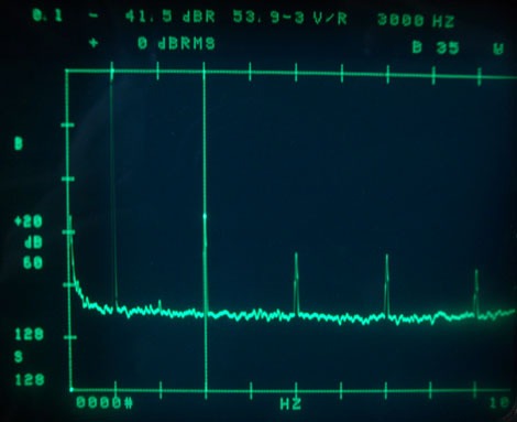
As can be seen, K3 is 41,5 dB below the fundamental. All odd order harmonics.
This poor performance is also expressed in the numbers found in the datasheet:
3 % - 8 % THD = -30 dB typical, -23 dB worst case @ -60 dB
Also found in the datasheet: Signal to noise ratio @ 0 dB is -96 dB which means noise is already very low.
Other than THD @ 0 dB which is very high: -70 dB to -75 dB.
EC,
could you please explain why you worry about loosing one LSB in PSU noise while at the same time the chip performs so badly on THD ?
You have -70 dB distortion and want to push a -96 dB noise floor to the limit ?
For what ? To better reveal the terrible distortion ?
Distortion detoriates resolution.
I tested nearly all available multibit DACs up to 20 bits and it showed that the good high resolution DACs have no better distortion figures than good 16 bit DACs at least at low level.
Just the noise floor is pushed down by dynamic range in conjunction with os filters and higher bit numbers.
Result: The same distortion can be better heard against a blacker background.
For comparison, this is the multibit DAC that I use: Clean down below -60 dB
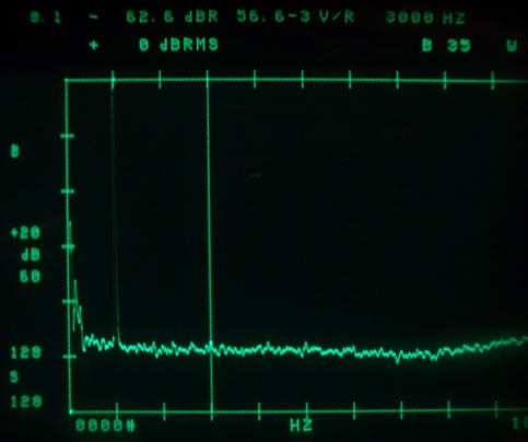
Back to the TDA1541A, the result is all that counts, not the hocuspocus inside.
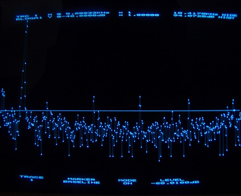
One rare golden S1 chip: All harmonics below -60 dB but only on one channel

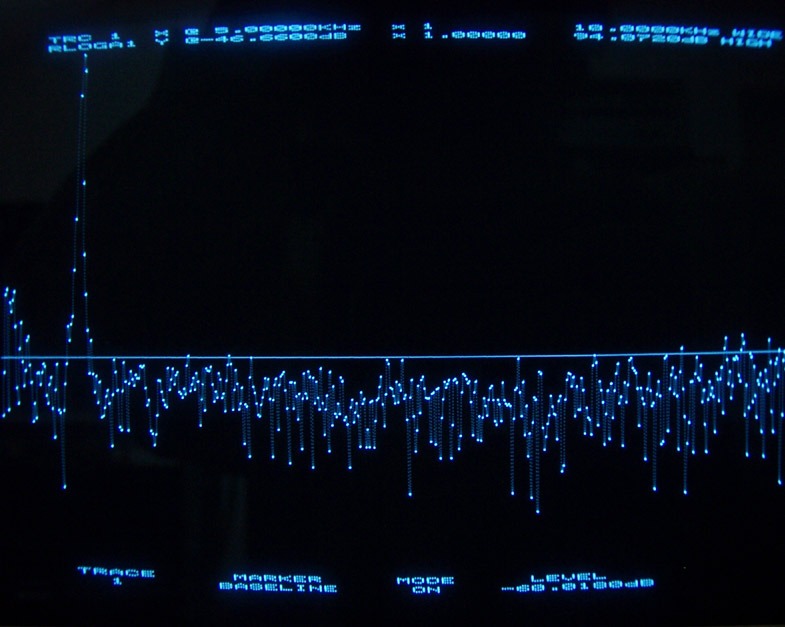
Unfortunately without oversampling it detoriates clearly:
Before you tell me that measurements tell nothing about sound... we know lots of people prefer junk food...
If I tell you that hamburgers are bad, because when you bring them to a lab, they will find unhealthy ingredients and artificial flavours, you might reply "but they taste so good" ... same thing.
By the way, also for the 1543, the output voltage compliance is 25mV, it may not have hard distortion like DACs with clipping diodes but distortion will rise in any case when exceeding the value.
Last edited:
no, Dynamic Element Matching and Continuous Calibration is very different things, read and try to understand documents carefullyDEM means Dynamic Element Matching, or in other words a continuous calibration system (6 MSBs)
"A Self-Calibration Technique for Monolithic High-Resolution D/A Converters" D. WOUTER J. GROENEVELD, HANS J. SCHOUWENAARS, HENK A. H. TERMEER, ANDCORNELIS A. A. BASTIAANSEN
"Dynamic Element Matching for High Acuracy Monolithic DAC" RUDY J. VAN DE PLASSCHE. IEEE JOURNAL OF SOLID-STATE CIRCUITS, VOL. SC-11, NO. 6, DEC 1976
"A Monolithic 14-Bit D/A Converter" RUDY J. VAN DE PLASSCHE , DICK GOEDHARD. IEEE JOURNAL OF SOLID-STATE CIRCUITS, VOL. SC-14, NO. 3, JUNE 1979
"A Monolithic Dual 16-Bit D/A Converter" HANS J. SCHOUWENAARS, EISE CAREL DIJKMANS, BEN M. J. KUP, AND ED J. M. VAN TUIJL.
Bernhard, yes 1543 is very badly sounding dac, and measurement and simply datasheet it perfectly show, 1541 without good DF (CXD1244,CXD1144,PMD100) also sounds far not perfectly
number of bits only defines signal to noise ratio but not distortions, distortion defines DNL, INL and glitch(if it is parallel dac)I tested nearly all available multibit DACs up to 20 bits and it showed that the good high resolution DACs have no better distortion figures than good 16 bit DACs at least at low level.
you forgot about filtering after DEM (14cap), after filtering currents are equalSo if your DEM runs at 250k .... you are getting 250k/44.1k corrections per sample period. Or some thing like that....
Last edited:
Hi Bernhard,
All we see here is a spectrum analysis of an unknown (TDA1543?) application. I would like to see TDA1543 production year, schematics and exact specifications of the application being tested here. This includes power supply specs, if the unit is battery or mains powered, I2S injection, I/V conversion method, and I2S timing jitter / spectrum. Is the spectrum analyzer battery or mains powered, and what bit depth / sample rate does it have?
My aim is minimizing timing errors. Timing errors are directly affected by power supply specs.
The terrible distortion you mention / measured? was never mentioned nor noticed by musicians (Dutch Conservatorium degree), and audiophiles that already listened to my TDA154x applications. So apparently it's not that "terrible" as you suggest.
This is true for TDA1541A. TDA1543 output compliance specs were simply copied from TDA1541A data sheet and are not valid. Proof, TDA1543 doesn't even function with 0V DC on the output, and it can easily generate up to 7Vpp ac on the outputs without significantly increasing THD, clearly proving there is no limitation imposed by diodes, nor diode non-linear characteristics.
These harmonics can easily be caused by I2S crosstalk, when driving ECL logic with a TTL level signal, it will over-drive the ECL input circuit, causing exactly this kind of crosstalk. It's likely that the channel located closest to the I2S input circuits picks-up most crosstalk and thus performs worse.
I always use 200mVpp I2S drive signals for this reason. I assume you used these I2S attenuators during measurement too. I also assume jitter amplitude would be low enough, not to affect measurements (say around 50ps rms). I further assume you used an isolated battery power supply in order to prevent ground loops affecting the measurement, and that the source was battery-operated too for similar reasons.
Next, it would be nice to have some proof that these kind of low level amplitude distortions are audible at all, using average volume setting. This test CD might help:
Test Discs/Sampler - Sheffield Labs - My Disc (Gold) - Audio Discs Australia - Sheffield Labs - My Disc (Gold)
Track 33 contains a 45-second sample of music recorded at a normal transfer level. Track 34 is the same sample but down 10 dB. Track 35 is down 20 dB. Track 36 is down 30 dB. Track 37 is down 40 dB. Track 38 is down 50 dB. Track 39 is down 60 dB. Track 40 is down 70 dB. Track 41 is digital black or all low bits or 0 bits.
Then there is the power amp crossover distortion that cannot be reduced to zero either, well unless you use a SE power amp like a A300B, but then you get problems with output transformer non-linearity errors, saturation "issues", and power supply noise / hum.
ps
I not only experimented with TDA1543 and TDA1541A DAC chips, I also tested AD1865 and PCM1702 among many others.
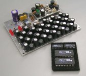
I attached a photograph of my AD1865 and PCM1702 collection with TDA1543 module as proof.
As can be seen, K3 is 41,5 dB below the fundamental. All odd order harmonics.
This poor performance is also expressed in the numbers found in the datasheet:
3 % - 8 % THD = -30 dB typical, -23 dB worst case @ -60 dB
All we see here is a spectrum analysis of an unknown (TDA1543?) application. I would like to see TDA1543 production year, schematics and exact specifications of the application being tested here. This includes power supply specs, if the unit is battery or mains powered, I2S injection, I/V conversion method, and I2S timing jitter / spectrum. Is the spectrum analyzer battery or mains powered, and what bit depth / sample rate does it have?
EC,
could you please explain why you worry about loosing one LSB in PSU noise while at the same time the chip performs so badly on THD ?
You have -70 dB distortion and want to push a -96 dB noise floor to the limit ?
For what ? To better reveal the terrible distortion ?
My aim is minimizing timing errors. Timing errors are directly affected by power supply specs.
The terrible distortion you mention / measured? was never mentioned nor noticed by musicians (Dutch Conservatorium degree), and audiophiles that already listened to my TDA154x applications. So apparently it's not that "terrible" as you suggest.
By the way, also for the 1543, the output voltage compliance is 25mV, it may not have hard distortion like DACs with clipping diodes but distortion will rise in any case when exceeding the value.
This is true for TDA1541A. TDA1543 output compliance specs were simply copied from TDA1541A data sheet and are not valid. Proof, TDA1543 doesn't even function with 0V DC on the output, and it can easily generate up to 7Vpp ac on the outputs without significantly increasing THD, clearly proving there is no limitation imposed by diodes, nor diode non-linear characteristics.
I tested nearly all available multibit DACs up to 20 bits and it showed that the good high resolution DACs have no better distortion figures than good 16 bit DACs at least at low level.
Just the noise floor is pushed down by dynamic range in conjunction with os filters and higher bit numbers.
Result: The same distortion can be better heard against a blacker background.
These harmonics can easily be caused by I2S crosstalk, when driving ECL logic with a TTL level signal, it will over-drive the ECL input circuit, causing exactly this kind of crosstalk. It's likely that the channel located closest to the I2S input circuits picks-up most crosstalk and thus performs worse.
I always use 200mVpp I2S drive signals for this reason. I assume you used these I2S attenuators during measurement too. I also assume jitter amplitude would be low enough, not to affect measurements (say around 50ps rms). I further assume you used an isolated battery power supply in order to prevent ground loops affecting the measurement, and that the source was battery-operated too for similar reasons.
Next, it would be nice to have some proof that these kind of low level amplitude distortions are audible at all, using average volume setting. This test CD might help:
Test Discs/Sampler - Sheffield Labs - My Disc (Gold) - Audio Discs Australia - Sheffield Labs - My Disc (Gold)
Track 33 contains a 45-second sample of music recorded at a normal transfer level. Track 34 is the same sample but down 10 dB. Track 35 is down 20 dB. Track 36 is down 30 dB. Track 37 is down 40 dB. Track 38 is down 50 dB. Track 39 is down 60 dB. Track 40 is down 70 dB. Track 41 is digital black or all low bits or 0 bits.
Then there is the power amp crossover distortion that cannot be reduced to zero either, well unless you use a SE power amp like a A300B, but then you get problems with output transformer non-linearity errors, saturation "issues", and power supply noise / hum.
ps
I not only experimented with TDA1543 and TDA1541A DAC chips, I also tested AD1865 and PCM1702 among many others.
I attached a photograph of my AD1865 and PCM1702 collection with TDA1543 module as proof.
Attachments
1543 is binary weighted type dac, calculate what would be DNL, INL (distortion) in real world components tolerances, thats why this type is not used for high resolution\low distortion DAC, max for 10-12bit, and this resolution you can see in TDA1543, designed for applications not demanding even middle quality level (such as old TV sets etc)All we see here is a spectrum analysis of an unknown (TDA1543?) application. I would like to see TDA1543 production year, schematics and exact specifications of the application being tested here. This includes power supply specs, if the unit is battery or mains powered, I2S injection, I/V conversion method, and I2S timing jitter / spectrum. Is the spectrum analyzer battery or mains powered, and what bit depth / sample rate does it have?
it is not so simpleTiming errors are directly affected by power supply specs.
"all learned in comparison"The terrible distortion you mention / measured? was never mentioned nor noticed by musicians (Dutch Conservatorium degree), and audiophiles that already listened to my TDA154x applications. So apparently it's not that "terrible" as you suggest.
1543 dont have internal ECL logicThese harmonics can easily be caused by I2S crosstalk, when driving ECL logic with a TTL level signal, it will over-drive the ECL input circuit, causing exactly this kind of crosstalk. It's likely that the channel located closest to the I2S input circuits picks-up most crosstalk and thus performs worse.
very funnyNext, it would be nice to have some proof that these kind of low level amplitude distortions are audible at all
can be, works of N. Shvydky from S-AUDIO "ZD-50" and S. Ageev "Superlinear amp" (for music studios), Halcro...Then there is the power amp crossover distortion that cannot be reduced to zero either
Last edited:
All we see here is a spectrum analysis of an unknown (TDA1543?) application. I would like to see TDA1543 production year, schematics and exact specifications of the application being tested here. This includes power supply specs, if the unit is battery or mains powered, I2S injection, I/V conversion method, and I2S timing jitter / spectrum.
I have the impression that you do not understand something that is very basic and important.
The low level distortion is determined by the chip linearity, more precisely: by the accuracy of the MSB and also a little by the next significant bit.
By nothing else
Why ?
PSU noise does not convert to THD. Jitter does not convert to THD. Any standard opamp I/V is capable of THD -90dB or better.
The -40 dB harmonics we talk about here, looking at the 1543 @ -60dB are by many magnitudes greater than the distortion contributed by the I/V and no I/V stage won't change that spectrum ever.
I explained that to you before but you seem to simply ignore it.
Is the spectrum analyzer battery or mains powered, and what bit depth / sample rate does it have?
Wow ! You're kidding with me !
The first analyzer that I used for the 1543 and the DAC below had a resolution of 12 bit which translates to a dynamic range of 70 dB.
When you measure a 16 bit DAC @ -60dB, the best noise floor you will see after 16x averaging will be around -65 dB independent of the dynamic range of the analyzer. So if the ADC is spurious free within the dynamic range, to measure a 16 bit DAC you will not need more than 12 bit of resolution.
Such an instrument very easyly shows the differences between a very poor DAC like the 1543 and a very good DAC as you see in the pictures.
The second analyzer that I used for the 1541A, and still use today, has 16 bit resolution = 94 dB dynamic range, sampling rate of 1MHz and a max. of 64000 aquisition points.
For signal preconditioning I use a matching ( same company ) dual wideband programmable gain preamplifier with a max. total gain of +52 dB.
However, to measure the low level distortion , no more than 12 bit is needed.
My aim is minimizing timing errors. Timing errors are directly affected by power supply specs.
Really... Below another quote:
Note how low the LSB current is, only 61 nano amperes! LSBs can easily drop below system noise level when power supplies aren't super clean, and output circuit fails to maintain extreme low noise levels.
The THD of the 1543 is -70dB even at 0 dB / full scale.
How can it be that you worry about one LSB to be lost in PSU noise, which would reduce the resolution to 15 bit, if the linearity of the DAC is only 12 bit ? Yes, -70 dB translates to 12 bit.

To "maintain extreme low noise levels" in the presence of terrible distortion is just ridiculous.
The terrible distortion you mention / measured? was never mentioned nor noticed by musicians (Dutch Conservatorium degree), and audiophiles that already listened to my TDA154x applications. So apparently it's not that "terrible" as you suggest.
When listening to a DAC like the 1543 or 14 bit 1540, nobody would perceive the sound as "distorted" because the music is already mostly "distorted" by the natural harmonics of voices and instruments. But "clean" sounds different, and I'm not talking about delta-sigma DACs.
Especially the crossover distortion caused by the MSB transition adds another unnatural distortion as I have previously explained and you have obviously ignored, so I won't repeat it.
This is true for TDA1541A. TDA1543 output compliance specs were simply copied from TDA1541A data sheet and are not valid. Proof, TDA1543 doesn't even function with 0V DC on the output, and it can easily generate up to 7Vpp ac on the outputs without significantly increasing THD, clearly proving there is no limitation imposed by diodes, nor diode non-linear characteristics.
I did not say it has diodes. I would like to see the FFT of 7Vpp.
I always use 200mVpp I2S drive signals for this reason. I assume you used these I2S attenuators during measurement too. I also assume jitter amplitude would be low enough, not to affect measurements (say around 50ps rms). I further assume you used an isolated battery power supply in order to prevent ground loops affecting the measurement, and that the source was battery-operated too for similar reasons.
Nonsense. To pick just one: Jitter translates to sidebands, not to THD.
Next, it would be nice to have some proof that these kind of low level amplitude distortions are audible at all, using average volume setting. This test CD might help:
Test Discs/Sampler - Sheffield Labs - My Disc (Gold) - Audio Discs Australia - Sheffield Labs - My Disc (Gold)
Track 33 contains a 45-second sample of music recorded at a normal transfer level. Track 34 is the same sample but down 10 dB. Track 35 is down 20 dB. Track 36 is down 30 dB. Track 37 is down 40 dB. Track 38 is down 50 dB. Track 39 is down 60 dB. Track 40 is down 70 dB. Track 41 is digital black or all low bits or 0 bits.
Thanks for your help, but it is clearly audible with any ordinary CD.
Also it is funny that on one side you hear the grass grow, on the other side you try to refuse the audibility of crossover distortion.
Then there is the power amp crossover distortion that cannot be reduced to zero either
Very simple: The power amp has a THD of below -90 dB but when you play a silent passage, you pass a signal that has -25 dB THD. The impact of the power amp is close to zero in this case.
I attached a photograph of my AD1865 and PCM1702 collection with TDA1543 module as proof.
Why not attach the schematic of your clock, I won't copy it.
Last edited:
If you do not like the TDA series DAC's, do not write on this post. As I told before, you must be in the ESS dac forum.
Nonsense.
1543 is binary weighted type dac, calculate what would be DNL, INL (distortion) in real world components tolerances, thats why this type is not used for high resolution\low distortion DAC, max for 10-12bit, and this resolution you can see in TDA1543, designed for applications not demanding even middle quality level (such as old TV sets etc)
The THD of the 1543 is -70dB even at 0 dB / full scale.
How can it be that you worry about one LSB to be lost in PSU noise, which would reduce the resolution to 15 bit, if the linearity of the DAC is only 12 bit ? Yes, -70 dB translates to 12 bit.
*lol* Math is a very exact science. TDA1543 is 12 bit max.
Concerning the audibility of low level distortion:
The distortion rises continiously from full scale down, that means a DAC that performs bad at -60 dB will also perform bad at -20 dB or -40 dB.
TDA 1543 has a THD of 0.1% at a playback level of -24 dB, see fig. 7 of datasheet.
-60dB level is only randomly picked and is industry standard for low level measurement, one could also use any other level signal in that range like -50 dB or -80 dB.
In other words, the 1543 distortion is not only extremly high at very low levels but also high on medium levels and still mediocre at high levels and 0dB / full scale.
more correctly: by all bits (but mostly MSB) and glitch (for example MSB change glitch produce 2nd harmonic)by the accuracy of the MSB and also a little by the next significant bit.
+1PSU noise does not convert to THD. Jitter does not convert to THD
in standart design only for middle frequencies and "static" signals, for yours measurements it is suitableAny standard opamp I/V is capable of THD -90dB or better
12bit is very optimistic, 11 more close to real world*lol* Math is a very exact science. TDA1543 is 12 bit max.
Last edited:
Poor specs of TDA
The problem here, IMHO, is the digital and analog filtering+oversampling. Both techniques contribute to an unnatural sound. I've tested the PCM1704K, no filtering, no oversampling, and it sounds very fine too. But not that kind of live sound like the TDA series. Forget about the FFT analyzer and more. Concentrate in hearing, and you'll see the light, if you want to do it.
The problem here, IMHO, is the digital and analog filtering+oversampling. Both techniques contribute to an unnatural sound. I've tested the PCM1704K, no filtering, no oversampling, and it sounds very fine too. But not that kind of live sound like the TDA series. Forget about the FFT analyzer and more. Concentrate in hearing, and you'll see the light, if you want to do it.
the problem is badly designed dacs, filtering has nothing to do with bad sound. Implementation is important...The problem here, IMHO, is the digital and analog filtering+oversampling. Both techniques contribute to an unnatural sound. I've tested the PCM1704K, no filtering, no oversampling, and it sounds very fine too. But not that kind of live sound like the TDA series. Forget about the FFT analyzer and more. Concentrate in hearing, and you'll see the light, if you want to do it.
12bit is very optimistic, 11 more close to real world
Could we agree on 12 "bad" bits ?

There must be something else in the equation than THD because if you listen to a new vinyl source the sound is very good too.
When you play music the dac pass a zillion more information than when making 'performance' tests. Not only the noise floor can be -90 (and even lower) db on tda1541 dac it can also sound better textured, this is only on that listening that I conclude the easiness to follow different musical lines on complex music like Bach cantatas. The modern dacs doesn’t give enough CONTRAST between textures of sound of different instruments at the same time.
What counts is this 70-75 DB of music - for most sound systems, this is where the music is and where we should focus, slew rate, inter-modulation, time distortions, transient distortions, mixed frequency integrity etc!!!
This kind of thd arguments don’t help others to get their tda1541 improve over the 1985 designs.
Natural sound
I've built a prototype, with tube outputs, good quality components, etc, etc. I do the listening tests with an own amp design, and 2 kind of transducers, my HD800 from Sennheiser, and my JAS audio Odin speakers. In both cases, the listening tests are very comfortable, very natural, and realistic. I have too measurement instrumentaion, but I only use them to check the results before test the dac with my ears. I think it's very important to feel the music, not only to feel the technology used to reproduce it, so, you can be an audiophile or a technophile. The last, after the time passes, will kill the good old designed products. "Engineer thinking" only, like I've done some years ago, it's not a good thing when designing audio devices of this level. You have to forget your prejudices, and unify your feelings with your engineering knowledge, not only one thing, but both, this is life, and this is music.
I've built a prototype, with tube outputs, good quality components, etc, etc. I do the listening tests with an own amp design, and 2 kind of transducers, my HD800 from Sennheiser, and my JAS audio Odin speakers. In both cases, the listening tests are very comfortable, very natural, and realistic. I have too measurement instrumentaion, but I only use them to check the results before test the dac with my ears. I think it's very important to feel the music, not only to feel the technology used to reproduce it, so, you can be an audiophile or a technophile. The last, after the time passes, will kill the good old designed products. "Engineer thinking" only, like I've done some years ago, it's not a good thing when designing audio devices of this level. You have to forget your prejudices, and unify your feelings with your engineering knowledge, not only one thing, but both, this is life, and this is music.
+1, but "performance" tests is too differentWhen you play music the dac pass a zillion more information than when making 'performance' tests
post 3174The modern dacs doesn’t give enough CONTRAST between textures of sound of different instruments at the same time.
the kind of DEM implementation (DWA etc) has ALL multilevels DS DACsDid you've tested the SM5865?. It has a newly designed DEM, and a lot of features
+1"Engineer thinking" only, like I've done some years ago, it's not a good thing when designing audio devices of this level.
- Home
- Source & Line
- Digital Line Level
- Building the ultimate NOS DAC using TDA1541A