Re: DI4T PCBs
what changes must be made to the above boards for this change:
I'm assuming these changes would be beneficial for the DI16 as well?
I'm planning on ordering the tube output once the DI16UTOS boards are made available for sale. I'm hoping that this will be very, very soon")
-ecdesigns- said:1 x TUBEPS.
2 x TUBEDIF. [/B]
what changes must be made to the above boards for this change:
-ecdesigns- said:- Tube-only output, (increased gain, higher twin cathode follower bias, gyrators & current sources removed)
I'm assuming these changes would be beneficial for the DI16 as well?
I'm planning on ordering the tube output once the DI16UTOS boards are made available for sale. I'm hoping that this will be very, very soon
Zoran said:I found this interesting for clock managing...
CDCM7005 (RGZ)- spqfp 48pin packge
from TI
please take a look.
cheers
I also stepped over it the other day. Seems to be very interesting.
Hi luvdunhill,
I will update both partslist and assembly instructions soon.
TUBEPS module:
D8, not placed
D11, 180V / 1.3W
R6 connects from T3 drain to anode pad of D8
T3 High-voltage N-MOSFET
Add 22uF / 400V, ( - ) to GND, ( + ) 33K to cathode D11 & 1K to T3 gate.
This converts the HV series regulator into a modified HV teddyreg.
The TUBEDIF modules:
R1,R6 2K2
R2,R5,R9 wire link
R3,R4 2K5 (Vishay S102 or Arcol)
R7,R9 not placed
R10,R11 1K
R17 12K/1W (Beyschlag)
C4 3.3uF/800V Audyn plus, and 7.5nF polypropylene bypass.
1000uF/50V placed in parallel with D5 (plus to GND, minus to anode)
D1 ... D3 not placed
T1 ... 4 removed
T1 & T2, wire link between b & e
T3 & T4, wire link between c & e
U1, replaced by 13K7 (Arcol)
V1 JJ ECC83S balanced/matched, gold pin, cryogenic treated (Cryoset)
V2 JJ ECC82 balanced/matched, gold pin, cryogenic treated (Cryoset)
This will improve both stability and resolution, it will also increase gain to the required level for passive I/V.
Passive I/V resistors are connected directly to the grids of V1:
4 x TDA1541A (2 x 8mA / 2 x 320mV), 2 x 40R, reference GND.
4 x TDA1543 (2 x 4mA / 2 x 320mV), 2 x 80R. Reference, 2.5V.
Yes, the DI16 will benefit from a passive I/V with tube amplification.
If you are in a hurry, I have some spare pre-assembled & tested UTOS2 and LRM1 modules.
what changes must be made to the above boards for this change:
I will update both partslist and assembly instructions soon.
TUBEPS module:
D8, not placed
D11, 180V / 1.3W
R6 connects from T3 drain to anode pad of D8
T3 High-voltage N-MOSFET
Add 22uF / 400V, ( - ) to GND, ( + ) 33K to cathode D11 & 1K to T3 gate.
This converts the HV series regulator into a modified HV teddyreg.
The TUBEDIF modules:
R1,R6 2K2
R2,R5,R9 wire link
R3,R4 2K5 (Vishay S102 or Arcol)
R7,R9 not placed
R10,R11 1K
R17 12K/1W (Beyschlag)
C4 3.3uF/800V Audyn plus, and 7.5nF polypropylene bypass.
1000uF/50V placed in parallel with D5 (plus to GND, minus to anode)
D1 ... D3 not placed
T1 ... 4 removed
T1 & T2, wire link between b & e
T3 & T4, wire link between c & e
U1, replaced by 13K7 (Arcol)
V1 JJ ECC83S balanced/matched, gold pin, cryogenic treated (Cryoset)
V2 JJ ECC82 balanced/matched, gold pin, cryogenic treated (Cryoset)
This will improve both stability and resolution, it will also increase gain to the required level for passive I/V.
Passive I/V resistors are connected directly to the grids of V1:
4 x TDA1541A (2 x 8mA / 2 x 320mV), 2 x 40R, reference GND.
4 x TDA1543 (2 x 4mA / 2 x 320mV), 2 x 80R. Reference, 2.5V.
I'm assuming these changes would be beneficial for the DI16 as well?
Yes, the DI16 will benefit from a passive I/V with tube amplification.
I'm planning on ordering the tube output once the DI16UTOS boards are made available for sale. I'm hoping that this will be very, very soon
If you are in a hurry, I have some spare pre-assembled & tested UTOS2 and LRM1 modules.
Hi mikelm,
These are high quality precision resistors, I need high-quality audio resistors. For passive I/V conversion, copper wire resistors clearly outperform bulk metal foils by a large margin, as they provide much higher resolution and better tonal balance.
That was my first impression too, until I tested the copper wire resistors. However, I do like bulk metal foils for (local) feedback.
another simpler but more expensive option would be to use a very high quality commercial resistor such a Caddock TF020.
These are high quality precision resistors, I need high-quality audio resistors. For passive I/V conversion, copper wire resistors clearly outperform bulk metal foils by a large margin, as they provide much higher resolution and better tonal balance.
These sound truly excellent - smooth, detailed & neutral.
That was my first impression too, until I tested the copper wire resistors. However, I do like bulk metal foils for (local) feedback.
-ecdesigns- said:Hi mikelm,
These are high quality precision resistors, I need high-quality audio resistors. For passive I/V conversion, copper wire resistors clearly outperform bulk metal foils by a large margin, as they provide much higher resolution and better tonal balance.
That was my first impression too, until I tested the copper wire resistors. However, I do like bulk metal foils for (local) feedback.
Caddock TF020 are not bulk foil resistors and I suggested them because they sound very good indeed and not for any other objective reason e.g. because they are precision.
I have not heard copper wire resistors so i cannot comment but I get the impression that you have not heard constantan wire or TF020 resistors. If that is the case how can u have any idea what they sound like ?
The main point I am trying to convey is that there is not a direct relationship between the specific resistance of a resistive element and noise so simply choosing the most conductive element for a resistor is not necessarily the best way to go.
I would say though that most commercially available resistors sound atrocious so paying attention to this variable can reap rich sonic rewards
cheers
mike
-ecdesigns- said:... I am no longer using any computer output (SPDIF nor USB) as I can't get bit-perfect output from my iMac / Mac OSX anymore, after recent software updates (iTunes / Quicktime), the soundmixer now seems to be active all the time (up/down sampling), and prevents bit-perfect playback, this causes significant sound quality degradation (very clearly audible). I suspect usable output resolution is now reduced to 14 .. 15 bits.
It seems that achieving bit-perfect playback requires constant tweaking / monitoring, and I just don't like that.
So I am now using Apple airport express module. It does provide bit-perfect output regardless of OS / application, as it just receives files over the (wireless) network.
I presume you are using the 3.5mm combined audio/optical socket on the output of the airport express to toslink? I presume this outputs un-mangled PCM? If so would this also be the case from the same socket on the back of your Mac, assuming it has one? My 'music' MacMini has the same 3.5mm combined audio/optical socket on the back, would this output the same unmangleded PCM?
Just wondering as it would save an airport Express. Is there any length to the limit of these optical cables? Any recommendations for such cables.
Hi mikelm,
I have tried Vishay bulk metal foils for passive I/V (both 20 and 40 Ohms), and was referring to my experiences with these resistors. I also tried both NiCr and Manganin wirewound resistors for passive I/V,
Caddock uses so called Tetrinox complex oxide resistor film (metal oxide), and resistance values are specified between 1 K Ohm and 125 M Ohm. These resistors are primarily designed for high precision. I am not sure about this specific metal oxide mixture, but I know that metal oxide resistors in general produce more noise and grain, compared to metal film resistors.
If I am correct, Vishay bulk metal foils are constructed from a NiCr film, and the datasheets aso indicate very low noise levels (noise-free component).
The question remains, what happens with resistor noise when an ac current runs through it, given the limited resistor wattage (TF020 is specified at 0.33W, S102 is specified at 0.6W).
It's known that higher resistor values produce more noise, and it's advised to keep resistance values below 1K Ohm if possible, for low noise applications. It's also known that higher wattage resistors, made of the same material, will produce less noise.
My experience is that one single resistor can already make or break sound quality, I have very good experience with resistors that produce lowest possible noise (bulk metal foil and wirewound resistors). The impact on sound quality is a dramatic increase in both transparency and resolution.
have not heard copper wire resistors so i cannot comment but I get the impression that you have not heard constantan wire or TF020 resistors. If that is the case how can u have any idea what they sound like ?
I have tried Vishay bulk metal foils for passive I/V (both 20 and 40 Ohms), and was referring to my experiences with these resistors. I also tried both NiCr and Manganin wirewound resistors for passive I/V,
Caddock TF020 are not bulk foil resistors and I suggested them because they sound very good indeed and not for any other objective reason e.g. because they are precision.
Caddock uses so called Tetrinox complex oxide resistor film (metal oxide), and resistance values are specified between 1 K Ohm and 125 M Ohm. These resistors are primarily designed for high precision. I am not sure about this specific metal oxide mixture, but I know that metal oxide resistors in general produce more noise and grain, compared to metal film resistors.
If I am correct, Vishay bulk metal foils are constructed from a NiCr film, and the datasheets aso indicate very low noise levels (noise-free component).
The question remains, what happens with resistor noise when an ac current runs through it, given the limited resistor wattage (TF020 is specified at 0.33W, S102 is specified at 0.6W).
It's known that higher resistor values produce more noise, and it's advised to keep resistance values below 1K Ohm if possible, for low noise applications. It's also known that higher wattage resistors, made of the same material, will produce less noise.
My experience is that one single resistor can already make or break sound quality, I have very good experience with resistors that produce lowest possible noise (bulk metal foil and wirewound resistors). The impact on sound quality is a dramatic increase in both transparency and resolution.
Hi rjbaldwin,
Yes I am using so called mini-TOSLINK output from the airport express module.
It's important to use a good quality TOSLINK optical cable WITHOUT 3.5mm adapter. Apple sells monster TOSLINK cables for the airport express module, these have glass-fibre instead of plastic fibres, this provides higher optical output (better S/N ratio at the TOSLINK receiver module).
The Airport Express mini TOSLINK output provides bit-perfect playback (fixed 44.1/16, option to disable volume control).
The TOSLINK connection on my iMac does not, both volume control / audio mixer remain active.
The digital audio receiver must have lowest possible jitter, regardless of jitter blocking strategy used. This is best achieved using slave-clock mode & VCXO, and extensive tuning. I currently use CS8412 and CS8416 as these provide a slave clock option (BCK and WS can be set as input).
ALL signals generated / used in a DAC need to have lowest possible jitter, as these will inter-modulate (wireless, power supply traces, ground-bounce, and crosstalk), increasing timing jitter, and polluting analogue circuits.
It's best to use a dedicated digital audio interface like the Apple airport express or squeezebox (duet), attempting to achieve bit-perfect playback directly from a computer is often highly problematic due to the software mess.
Other big advantage is that you can place the (noisy) computer in another room, and use the (wireless) network interface to extend the distance between both computer and DAC. The computer network also provides error correction.
The TOSLINK cable length depends on cable quality (type of fibre optics), I currently use a 5 meter HQ interlink. Apple offers some good quality monster cables (TOSLINK to mini TOSLINK, available in both 1 and 2 meters).
I think it's most important to provide enough optical output, this basically means using high-quality glass fibre optics, and reduced interlink length.
TOSLINK (SPDIF) always causes interlink jitter, due to the fact that it transports both DATA and timing information in one single signal.
I presume you are using the 3.5mm combined audio/optical socket on the output of the airport express to toslink? I presume this outputs un-mangled PCM? If so would this also be the case from the same socket on the back of your Mac, assuming it has one?
Yes I am using so called mini-TOSLINK output from the airport express module.
It's important to use a good quality TOSLINK optical cable WITHOUT 3.5mm adapter. Apple sells monster TOSLINK cables for the airport express module, these have glass-fibre instead of plastic fibres, this provides higher optical output (better S/N ratio at the TOSLINK receiver module).
The Airport Express mini TOSLINK output provides bit-perfect playback (fixed 44.1/16, option to disable volume control).
The TOSLINK connection on my iMac does not, both volume control / audio mixer remain active.
The digital audio receiver must have lowest possible jitter, regardless of jitter blocking strategy used. This is best achieved using slave-clock mode & VCXO, and extensive tuning. I currently use CS8412 and CS8416 as these provide a slave clock option (BCK and WS can be set as input).
ALL signals generated / used in a DAC need to have lowest possible jitter, as these will inter-modulate (wireless, power supply traces, ground-bounce, and crosstalk), increasing timing jitter, and polluting analogue circuits.
Just wondering as it would save an airport Express. Is there any length to the limit of these optical cables? Any recommendations for such cables.
It's best to use a dedicated digital audio interface like the Apple airport express or squeezebox (duet), attempting to achieve bit-perfect playback directly from a computer is often highly problematic due to the software mess.
Other big advantage is that you can place the (noisy) computer in another room, and use the (wireless) network interface to extend the distance between both computer and DAC. The computer network also provides error correction.
The TOSLINK cable length depends on cable quality (type of fibre optics), I currently use a 5 meter HQ interlink. Apple offers some good quality monster cables (TOSLINK to mini TOSLINK, available in both 1 and 2 meters).
I think it's most important to provide enough optical output, this basically means using high-quality glass fibre optics, and reduced interlink length.
TOSLINK (SPDIF) always causes interlink jitter, due to the fact that it transports both DATA and timing information in one single signal.
It's best to use a dedicated digital audio interface like the Apple airport express or squeezebox (duet), attempting to achieve bit-perfect playback directly from a computer is often highly problematic due to the software mess.
This is a good solution to the bit-perfect problem, but to remain on the chip side it' s possible to have bit-perfect from PC (with low jitter).
My recipe:
- Old pc (in my case: 500MHz PIII with big fanless heatsink + 512MB + HD + fanless SilverStone PSU)
- Envy24* based sound card (TOS in + out with the feature to sync on TOS in - chip on ebay)
- Linux with recent alsa driver
- MPD player configured to use the hw device
- DAC with a master clock and a reclocking scheme that generate a blank spdif signal to send to the TOS in of the sound card to have all in sync (a solution proposed in several post in this forum by peufeu and alexandre - to my knowledge)
ciao
andrea
-ecdesigns- said:Caddock uses so called Tetrinox complex oxide resistor film (metal oxide), and resistance values are specified between 1 K Ohm and 125 M Ohm. These resistors are primarily designed for high precision. I am not sure about this specific metal oxide mixture, but I know that metal oxide resistors in general produce more noise and grain, compared to metal film resistors.
I agree most metal oxide resistors sound dreadful - these ones are rather different - Caddock themselves are not sure why audiophiles are choosing this series - but they are aware that they are.
-ecdesigns- said:My experience is that one single resistor can already make or break sound quality
I completely agree - even in unexpected postions.
I suspect that wire wound resistors will either have some extra inductance or some extra capacitance ( or both ) which depending on the different implementations could enhance or subtract from subjective sound quality - but I am interested to hear the ones u like.
I also strongly recommend u try constantan wire - especially if u need low values.
mike
-ecdesigns- said:The Airport Express mini TOSLINK output provides bit-perfect playback (fixed 44.1/16, option to disable volume control).
The TOSLINK connection on my iMac does not, both volume control / audio mixer remain active.
Thanks ecdesigns, for all your useful advice. I was mistakenly under the impression that the optical out from my computer was indeed 'bit perfect'. How did you find out it was not? Is there an easy way of measuring it, compared to say the output from an Airport Express?
The digital audio receiver must have lowest possible jitter, regardless of jitter blocking strategy used. This is best achieved using slave-clock mode & VCXO, and extensive tuning. I currently use CS8412 and CS8416 as these provide a slave clock option (BCK and WS can be set as input).
I have read elsewhere that the output from the Airport Express is quite jittery and needs to be re-clocked? I look forward to buying the new boards when available, I have 10 TDA1541A's on the shelf and this seems a very good project. Any idea when they may be available?
Hi rjbaldwin,
I always compare digital audio sources with my CD reference transport digital output. Both USB and TOSLINK connection on the iMac clearly reduce sound quality (resolution) when compared to the Apple airport express module output. I am pretty sure that when Apple would provide a similar fixed volume & 44.1/16 option in iTunes for on-board TOSLINK & USB outputs, just like they did with the Apple airport express module, sound quality would improve significantly.
Currently I would rate interface sound quality as follows, starting with the best:
1) TOSLINK, Apple airport express module (fixed volume selected) & CD reference transport.
2) TOSLINK, iMac on-board output, volume setting to max, sound disabled in all other applications, equalizer disabled.
3) USB (PCM2706), same settings as (2).
There are ways of measuring / verifying it like file compare, when using high-performance audio sets, the differences in sound quality are clear as day.
Note that I use extensive jitter-blocking techniques in the DI4T that should reduce the effect of interface jitter to very low values, so if there are differences in sound quality, they are mainly caused by non-bit perfect playback.
All TOSLINK / SPDIF sources generate jitter, due to the fact that SPDIF contains both DATA and timing information (bi-phase modulation). Bits are identified by either one or two clock transitions / bit (2.8224 or 5.6448 MHz), when the SPDIF interlink has limited bandwidth, the frequency shift will induce a phase shift. The smaller the bandwidth (TOSLINK) the higher the phase shift. These phase shifts then translate to increased jitter.
I can verify that the Apple airport express TOSLINK output isn't the cleanest, but effective jitter blocking techniques can still cope with this.
The SPDIF generation logic (VLSI) will always have significant on-chip ground-bounce, together with a lousy clock this will ensure relatively high SPDIF timing jitter, even before sending it over an interlink.
I am currently testing a SPDIF cleaner, a circuit that synchronously reclocks the SPDIF signal, prior to feeding it into the main SPDIF receiver.
It's a quite simple circuit that's based on using a PLL from a second SPDIF receiver chip to drive a D-flip-flop through inverted MCLK (11.2896 MHz). The D flip-flop outputs a much cleaner copy of the original SPDIF signal, so the main SPDIF receiver has an easier job to further reduce jitter (cascaded PLLs).
My theory is that all frequencies used / generated in a DAC will inter-modulate, increasing both timing jitter, and analogue output signal pollution. This is why I want to reduce SPDIF jitter despite using an effective source jitter blocking strategy like with the VCXO.
It's VERY important to use effective power supply decoupling and loop filters in the SPDIF receiver.
I currently use the CS8412 in the DI4 mainboard prototype, so I will use it as example:
Both analogue and digital ground are each decoupled by soldering 3 x 100nF COG / NPO 1206 SMD capacitors in parallel, directly to the chip pins as close to the plastic housing as possible, this ensures lowest inductance and efficient power supply decoupling.
The loop filter was modified as follows:
3 x 1nF 1206 NPO capacitor in parallel, soldered directly between FILT & analogue GND, on the chip pins, as close to the plastic housing as possible
2 x 100nF COG / NPO 1206 (parallel) in series with 2 x MELF 1K Ohm 1206 (parallel) between FILT and AGND.
This results in the following:
3nF between FILT and AGND, 200nF in series with 500R between FILT and AGND.
Thanks ecdesigns, for all your useful advice. I was mistakenly under the impression that the optical out from my computer was indeed 'bit perfect'. How did you find out it was not? Is there an easy way of measuring it, compared to say the output from an Airport Express?
I always compare digital audio sources with my CD reference transport digital output. Both USB and TOSLINK connection on the iMac clearly reduce sound quality (resolution) when compared to the Apple airport express module output. I am pretty sure that when Apple would provide a similar fixed volume & 44.1/16 option in iTunes for on-board TOSLINK & USB outputs, just like they did with the Apple airport express module, sound quality would improve significantly.
Currently I would rate interface sound quality as follows, starting with the best:
1) TOSLINK, Apple airport express module (fixed volume selected) & CD reference transport.
2) TOSLINK, iMac on-board output, volume setting to max, sound disabled in all other applications, equalizer disabled.
3) USB (PCM2706), same settings as (2).
There are ways of measuring / verifying it like file compare, when using high-performance audio sets, the differences in sound quality are clear as day.
Note that I use extensive jitter-blocking techniques in the DI4T that should reduce the effect of interface jitter to very low values, so if there are differences in sound quality, they are mainly caused by non-bit perfect playback.
I have read elsewhere that the output from the Airport Express is quite jittery and needs to be re-clocked? I look forward to buying the new boards when available, I have 10 TDA1541A's on the shelf and this seems a very good project. Any idea when they may be available?
All TOSLINK / SPDIF sources generate jitter, due to the fact that SPDIF contains both DATA and timing information (bi-phase modulation). Bits are identified by either one or two clock transitions / bit (2.8224 or 5.6448 MHz), when the SPDIF interlink has limited bandwidth, the frequency shift will induce a phase shift. The smaller the bandwidth (TOSLINK) the higher the phase shift. These phase shifts then translate to increased jitter.
I can verify that the Apple airport express TOSLINK output isn't the cleanest, but effective jitter blocking techniques can still cope with this.
The SPDIF generation logic (VLSI) will always have significant on-chip ground-bounce, together with a lousy clock this will ensure relatively high SPDIF timing jitter, even before sending it over an interlink.
I am currently testing a SPDIF cleaner, a circuit that synchronously reclocks the SPDIF signal, prior to feeding it into the main SPDIF receiver.
It's a quite simple circuit that's based on using a PLL from a second SPDIF receiver chip to drive a D-flip-flop through inverted MCLK (11.2896 MHz). The D flip-flop outputs a much cleaner copy of the original SPDIF signal, so the main SPDIF receiver has an easier job to further reduce jitter (cascaded PLLs).
My theory is that all frequencies used / generated in a DAC will inter-modulate, increasing both timing jitter, and analogue output signal pollution. This is why I want to reduce SPDIF jitter despite using an effective source jitter blocking strategy like with the VCXO.
It's VERY important to use effective power supply decoupling and loop filters in the SPDIF receiver.
I currently use the CS8412 in the DI4 mainboard prototype, so I will use it as example:
Both analogue and digital ground are each decoupled by soldering 3 x 100nF COG / NPO 1206 SMD capacitors in parallel, directly to the chip pins as close to the plastic housing as possible, this ensures lowest inductance and efficient power supply decoupling.
The loop filter was modified as follows:
3 x 1nF 1206 NPO capacitor in parallel, soldered directly between FILT & analogue GND, on the chip pins, as close to the plastic housing as possible
2 x 100nF COG / NPO 1206 (parallel) in series with 2 x MELF 1K Ohm 1206 (parallel) between FILT and AGND.
This results in the following:
3nF between FILT and AGND, 200nF in series with 500R between FILT and AGND.
Hi,
about copper wire resistor:
i just tested them in speaker crossover and they worked perfectly.
Before i have good quality wirewound resistors. Difference are not small at all. Sound it more fluently (liquid) , clear, transparent. I will stay here with that.
They are made from Johns instructions: wire twisted, folded (to get
non-inductive), twisted and rolled on body. It is quite a lot of work with that, but results are best for me.
Thanks John again.
About DI DAC:
i went from DI16 to DI8X4 but best works with 4 single TDA1543s. Sound is more clear now quite amazing. To get rid of Op-amps is good idea, even very good LM4562. It seems still cannot handle complex signal perfectly. I use now IV Arcol resistors and 1 diff- opamp.
Input signals attenuators and level shifter makes also big diffence in
sound. Last version Johns works them best.
With 4 single DACs runs now cool (no hot towers, warm opamps, and hot toroids).
Little off topic:
I was plan to report about Johns Sonic resonators SR80. And before that i would test them to other friends, to get more objective view of sound quality.
Not completely finish yet (some small upgrades and to make the more rigid). It is complicated design.
By using them already 2 months, i like them very much and they are first speakers that my 4 years old daughter likes and starting dancing on music. Good describe would be very balanced, transparent sound, very fast bass responce, handle easily 30Hz (even with one speaker i could make room to resonate; only for testing). As they are omnipolar, sound waves are difference as usual speakers; no sweet spot, they recreate very good soundstage with realistic depth. I cant find any complain about them.
I wanted to share.
And also thanks for all shares and help to John.
Best regards,
Bostjan
SPDIF cleaner
Hi a333bt,
Thanks for sharing this,
Yesterday I tested the SPDIF cleaner. This device takes an SPDIF signal (TOSLINK / COAX), and basically reclocks it using a second SPDIF receiver.
The cleaned-up SPDIF signal is then fed to a second SPDIF receiver chip that derives the I2S DATA signal from this clean SPDIF input signal, while receiving low-jitter timing signals from a VCXO and dividers.
So I now basically got 3 PLLs, one in the SPDIF cleaner, one in the SPDIF receiver, and one in the VCXO.
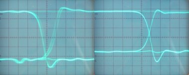
I attached an oscillogram, on the left is the output signal of a TOSLINK receiver connected through a 5 meter TOSLINK interlink with plastic fiber- optics to my Apple airport express module. On the right is the cleaned-up SPDIF signal that's fed to my DI4T.
Hi a333bt,
Thanks for sharing this,
Yesterday I tested the SPDIF cleaner. This device takes an SPDIF signal (TOSLINK / COAX), and basically reclocks it using a second SPDIF receiver.
The cleaned-up SPDIF signal is then fed to a second SPDIF receiver chip that derives the I2S DATA signal from this clean SPDIF input signal, while receiving low-jitter timing signals from a VCXO and dividers.
So I now basically got 3 PLLs, one in the SPDIF cleaner, one in the SPDIF receiver, and one in the VCXO.
I attached an oscillogram, on the left is the output signal of a TOSLINK receiver connected through a 5 meter TOSLINK interlink with plastic fiber- optics to my Apple airport express module. On the right is the cleaned-up SPDIF signal that's fed to my DI4T.
Attachments
Again on DEM reclock
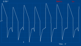
I have built ecdesign's DEM reclock. The output from the 74LS161 is fed to pin 16 through a 680 ohm/330 ohm divider and the 470 pF capacitor disconnected from pin 17. The signal at pin 16 is showed in the attached picture. Amplitude is less than 1 Vpp.
After the mod focus seems to be a little better, but prior the mod (470 pF directly soldered under pin 16 and pin 17, ultra-short connections), sound seemed a little cleaner.
Questions:
1) I could not find a 74HC161. Does the LS series have a lower performance in this circuit?
2) The signal at pin 16 looked instable and my scope (Velleman PCS500) did not trigger it for most of the time. It also had a slightly variable amplitude over the time. Was that signal suitable for the purpose?
Any comment?
Best regards.
Paul
Attachments
DEM clock
Hi Sandor,
There are many factors affecting DAC sound quality, the DEM clock is only one of them, and can only perform correctly when the other circuits are performing optimally as well.
One thing is for sure, the original DEM clock oscillator shows massive data-related jitter way above 1ns rms. This translates to data-related bit-errors (active divider efficiency).
The 352.8 KHz DEM clock reduces this jitter to approx. 50 ... 200ps depending on BCK jitter and routing.
In order to achieve highest possible DAC performance, ALL introduced errors like distortion, crosstalk and jitter must not correlate to the audio data. It's better to have 1ns jitter with a "white-noise" spectrum than 100ps jitter that correlates to the digital audio data.
This could explain why TOSLINK producing lower jitter amplitude, but data-related jitter, generally performs worse than coax producing higher jitter that correlates less with the audio data.
Correct DEM reclocking enhances resolution by reducing bit errors (more accurate averaging in the active divider stages of the TDA1541A). As a result of this, other flaws in the DAC design may surface that need to be solved.
Routing is critical, GND return paths are critical. The 74HC161/74HCT616 needs a very low jitter clock. It could help to place a 100 Ohm damping resistor between 74HC*161 output pin and the wire that is routed to the DEM clock attenuator.
In general DAC lay-out is highly critical, and the routing of one single wire can already degrade sound quality. It's also important to use I2S attenuators for both DATA and WS signal (5K6 series resistor, 1K to GND, 3K3 to +5V). Crosstalk with the I2S DATA signal and other timing signals should be avoided / minimized.
Other problem is TDA1541A digital and analogue GND. DEM clock is referenced to AGND, the DEM clock generator is referenced to DGND. The correct DEM clock phase with respect to BCK is also important, so you could try inverting the DEM clock.
Finally the decoupling cap properties are very important when using higher DEM clock rates. I still have best results with BC components 470 series (stacked foil caps). Large "audiophile" decoupling capacitors have far too high inductance to effectively filter BCK and DEM clock pulses on the active divider outputs.
This also means that ALL decoupling caps need to have exclusive shortest (lowest inductance) path to AGND, every millimeter matters here. Most ideal would be soldering the decoupling caps directly between active divider output pins and AGND pin (so no other currents pass through the AGND decoupling return path).
Do realize that the frequencies present on the active divider outputs can be in excess of 2.8MHz, a large foil cap simply can't cope with these HF signals. Ceramics are unsuitable because of DC leakage currents, capacitance modulation, and drift.
Hi Sandor,
After the mod focus seems to be a little better, but prior the mod (470 pF directly soldered under pin 16 and pin 17, ultra-short connections), sound seemed a little cleaner.
There are many factors affecting DAC sound quality, the DEM clock is only one of them, and can only perform correctly when the other circuits are performing optimally as well.
One thing is for sure, the original DEM clock oscillator shows massive data-related jitter way above 1ns rms. This translates to data-related bit-errors (active divider efficiency).
The 352.8 KHz DEM clock reduces this jitter to approx. 50 ... 200ps depending on BCK jitter and routing.
In order to achieve highest possible DAC performance, ALL introduced errors like distortion, crosstalk and jitter must not correlate to the audio data. It's better to have 1ns jitter with a "white-noise" spectrum than 100ps jitter that correlates to the digital audio data.
This could explain why TOSLINK producing lower jitter amplitude, but data-related jitter, generally performs worse than coax producing higher jitter that correlates less with the audio data.
Correct DEM reclocking enhances resolution by reducing bit errors (more accurate averaging in the active divider stages of the TDA1541A). As a result of this, other flaws in the DAC design may surface that need to be solved.
Routing is critical, GND return paths are critical. The 74HC161/74HCT616 needs a very low jitter clock. It could help to place a 100 Ohm damping resistor between 74HC*161 output pin and the wire that is routed to the DEM clock attenuator.
In general DAC lay-out is highly critical, and the routing of one single wire can already degrade sound quality. It's also important to use I2S attenuators for both DATA and WS signal (5K6 series resistor, 1K to GND, 3K3 to +5V). Crosstalk with the I2S DATA signal and other timing signals should be avoided / minimized.
Other problem is TDA1541A digital and analogue GND. DEM clock is referenced to AGND, the DEM clock generator is referenced to DGND. The correct DEM clock phase with respect to BCK is also important, so you could try inverting the DEM clock.
Finally the decoupling cap properties are very important when using higher DEM clock rates. I still have best results with BC components 470 series (stacked foil caps). Large "audiophile" decoupling capacitors have far too high inductance to effectively filter BCK and DEM clock pulses on the active divider outputs.
This also means that ALL decoupling caps need to have exclusive shortest (lowest inductance) path to AGND, every millimeter matters here. Most ideal would be soldering the decoupling caps directly between active divider output pins and AGND pin (so no other currents pass through the AGND decoupling return path).
Do realize that the frequencies present on the active divider outputs can be in excess of 2.8MHz, a large foil cap simply can't cope with these HF signals. Ceramics are unsuitable because of DC leakage currents, capacitance modulation, and drift.
- Home
- Source & Line
- Digital Line Level
- Building the ultimate NOS DAC using TDA1541A