Dacapo voltages
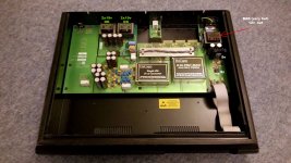
The two transformers on the mains card should all be putting out about 19v DC (after the rectifiers). If one has a low rail it is likely being dragged down by excessive loading (did you replace all those old 2200uf capacitors?). If the PCB tracks are corroded by rotten capacitors and you did repairs then checking that you re-instated the tracks correctly could be another place for your attention (The PCB is simple enough but I can tell you from experience that it is difficult to get a picture of a PCB that hasn't rotted so that you know what to aim for, only later issues of the board had capacitors that didn't leak and rot the PCB's).
The single transformer on the right side (looking from the front) is for the logic and is usually a couple of 9v windings in parallel (but I have seen a single higher current 9v winding used), fed into a bridge rectifier and then a couple of 317 to-220 package regulators. The PCB indicates 8v2 on the tab of one of them if memory serves correctly.
Hope that helps.
Please help me. What is the voltage from the transformers? I have one gives out 12v (hot!) Another pair goes 4 lines. 3 of them give 18-19v and one 16v (?!). It seems to me wrong.
The two transformers on the mains card should all be putting out about 19v DC (after the rectifiers). If one has a low rail it is likely being dragged down by excessive loading (did you replace all those old 2200uf capacitors?). If the PCB tracks are corroded by rotten capacitors and you did repairs then checking that you re-instated the tracks correctly could be another place for your attention (The PCB is simple enough but I can tell you from experience that it is difficult to get a picture of a PCB that hasn't rotted so that you know what to aim for, only later issues of the board had capacitors that didn't leak and rot the PCB's).
The single transformer on the right side (looking from the front) is for the logic and is usually a couple of 9v windings in parallel (but I have seen a single higher current 9v winding used), fed into a bridge rectifier and then a couple of 317 to-220 package regulators. The PCB indicates 8v2 on the tab of one of them if memory serves correctly.
Hope that helps.
That's right, the line on the 19th century was corrected by me. Capacitors have been replaced earlier.
It would be great to know exactly about the voltage (single transformer). I think it is subject to replacement .. but I'm afraid to spoil something by putting the voltage more than the nominal. But Dacapo is working at the same time.
Maybe someone else knows.
Thanks for the response and help!
Voltages
The transformers are just 15v - 0 - 15v - 0. If one is only putting out 16v after the rectifier and the transformer is getting hot then you have a problem that will likely cause premature failure of that transformer. They are a total pain to replace because of the pinouts (I had to replace one of mine and paid to have a custom wound transformer rather than chop up the PCB to make a cheaper one work).
Suggest that you put a small value resistor in series with the rectifier output and measure the voltage over it so that you can then calculate the current draw - repeat for the other rail from the same transformer and compare. If they aren't similar then the problem is not with your transformers.
I wrote it wrong, sorry. The problem now looks like this.
Attachments
Transformer problem
The tab of one of those regulators should be at 8v2 - if you have 9v then you may have shorted secondary windings where the heat has caused the insulation to fail (the transformer will get hotter still as a result of this).
I think this regulator feeds into further SMT 317 regulators used for the CS8412, ec.
Strongly suggest you replace this transformer before it fails and takes out half the logic on your DAC board!
I think this transformer is under sized anyway - it might be a good idea to replace this with a 30va 9v? (Check voltage!) toroidal transformer located towards the front of the case (there is loads of space there and it will be much easier than trying to get a drop-in replacement).
Last edited:
The tab of one of those regulators should be at 8v2 - if you have 9v then you may have shorted secondary windings where the heat has caused the insulation to fail (the transformer will get hotter still as a result of this).
I think this regulator feeds into further SMT 317 regulators used for the CS8412, ec.
Strongly suggest you replace this transformer before it fails and takes out half the logic on your DAC board!
I think this transformer is under sized anyway - it might be a good idea to replace this with a 30va 9v? (Check voltage!) toroidal transformer located towards the front of the case (there is loads of space there and it will be much easier than trying to get a drop-in replacement).
Thank you for this information! This is exactly what I needed!
Hello gentlemen,
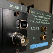
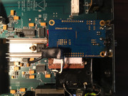
Can't help to show off a bit: did you know there was a special limited edition of Ordinal with a USB input?
Well, I'm not sure JW has ever heard about this version, but I got it now... After months of struggle with the faulty left channel (post #795), I finally found a capable technician who found the problem in a couple of hours. All caps were replaced with long-life Rubicons, I liked the sound a lot - but had not much use for the Ordinal, since 95% of my digital music is on a server, not on CDs.
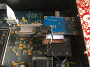
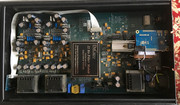
So the Ordinal got a brand new XMOS board - i2soverusb by a local company named JL Sounds. The same board is used by quite a few high-end brands (Thrax Audio for sure, can't name the others). It's connected in parallel to the existing S/PDIF input. The tech managed to squeeze in a separate power supply (powering this board over USB is not a great idea, I've heard that before) - and the results are fantastic.
In terms of musicality, the old Brit outplayed my other DAC - custom full dual-mono configuration with Delta-Sigma Asahi Kasei DAC chips, precision oscillators, three toroidal transfomers and the same XMOS board - straight away. Of course, in a side-by-side comparison the sound of the Ordinal is much rougher, and the level of detail from a hi-res file is unobtainable with the old technology - but the scene is tighter and better laid out for sheer listening pleasure.
I'm not so technically savvy myself to explain all the details, but could ask the technician, if there are any specific questions.
Can't help to show off a bit: did you know there was a special limited edition of Ordinal with a USB input?
Well, I'm not sure JW has ever heard about this version, but I got it now... After months of struggle with the faulty left channel (post #795), I finally found a capable technician who found the problem in a couple of hours. All caps were replaced with long-life Rubicons, I liked the sound a lot - but had not much use for the Ordinal, since 95% of my digital music is on a server, not on CDs.
So the Ordinal got a brand new XMOS board - i2soverusb by a local company named JL Sounds. The same board is used by quite a few high-end brands (Thrax Audio for sure, can't name the others). It's connected in parallel to the existing S/PDIF input. The tech managed to squeeze in a separate power supply (powering this board over USB is not a great idea, I've heard that before) - and the results are fantastic.
In terms of musicality, the old Brit outplayed my other DAC - custom full dual-mono configuration with Delta-Sigma Asahi Kasei DAC chips, precision oscillators, three toroidal transfomers and the same XMOS board - straight away. Of course, in a side-by-side comparison the sound of the Ordinal is much rougher, and the level of detail from a hi-res file is unobtainable with the old technology - but the scene is tighter and better laid out for sheer listening pleasure.
I'm not so technically savvy myself to explain all the details, but could ask the technician, if there are any specific questions.
Are there any dead DaCapo’s available
I bought a dead DaCapo and made a battery PSU for my working DaCapo. Then I bought another dead DeCapo to house a Moode audio player project - problem was that it was an easy repair so now I’m back in need of another dead ‘un.
Does anyone have anything they’d be interested in selling?
I bought a dead DaCapo and made a battery PSU for my working DaCapo. Then I bought another dead DeCapo to house a Moode audio player project - problem was that it was an easy repair so now I’m back in need of another dead ‘un.
Does anyone have anything they’d be interested in selling?
USB
It is interesting!
Can I have a larger photo?
What formats now work or only 16 \\ 44?
Hello!Hello gentlemen,
Can't help to show off a bit: did you know there was a special limited edition of Ordinal with a USB input?
Well, I'm not sure JW has ever heard about this version, but I got it now... After months of struggle with the faulty left channel (post #795), I finally found a capable technician who found the problem in a couple of hours. All caps were replaced with long-life Rubicons, I liked the sound a lot - but had not much use for the Ordinal, since 95% of my digital music is on a server, not on CDs.
So the Ordinal got a brand new XMOS board - i2soverusb by a local company named JL Sounds. The same board is used by quite a few high-end brands (Thrax Audio for sure, can't name the others). It's connected in parallel to the existing S/PDIF input. The tech managed to squeeze in a separate power supply (powering this board over USB is not a great idea, I've heard that before) - and the results are fantastic.
In terms of musicality, the old Brit outplayed my other DAC - custom full dual-mono configuration with Delta-Sigma Asahi Kasei DAC chips, precision oscillators, three toroidal transfomers and the same XMOS board - straight away. Of course, in a side-by-side comparison the sound of the Ordinal is much rougher, and the level of detail from a hi-res file is unobtainable with the old technology - but the scene is tighter and better laid out for sheer listening pleasure.
I'm not so technically savvy myself to explain all the details, but could ask the technician, if there are any specific questions.
It is interesting!
Can I have a larger photo?
What formats now work or only 16 \\ 44?
Last edited:
Hello John.
I got DaCapo, which managed to fix it.
This is a very good sound, perhaps even amazing!
I begin to study electronics and a few thoughts haunt me.
1. Why are there a lot of capacitors in Dacapo, but there are no CLC or CRC filters? This is considered useful for sound and is constantly found in circuits ..
2. No one tried to change the OPA604, because now there is an AD8066 for example, which should be much better. I would try, but I don’t understand in what mode OpAmp works ?! Usually, after DAC, there is an I \\ U converter, adder, filter .. I cannot understand why OpAmp is single and single! And with all this managed to do without capacitors at the output. How is this possible? !! =)
PS.: And thanks again for such a beautiful thing, I am very proud that I have this DAC! СПАСИБО!
Hi Aparutusonitus,
Sorry I made an error in the PLM to PDM decoding section (I worked with the SAA7350 17 years ago now), pls. see the corrected schematic (Note the addition of the “AND” Gates). The 2 series connected AND Gates are to compensate for the propagation delay of the D-Latch, without you would get short "runt" pulses – Sorry somewhat crude but works...
The output from the DAC section should not be considered “Balanced” as in the conventional sense of the term. The DAC section has two outputs, but they need to be correctly summed to fully reconstruct the Modulators intended output. Only once both outputs have been correctly summed will you have the correct output. This is the function of the differential OPAMP’s.
In fact, only the crossed coupled differential OPAMP’s generate the correct “Balanced output”.
1. The Common Mode component (2.5V) is rejected.
2. With this crossed coupled arrangement both “arms” of the DAC element see the SAME load impendence – this is very VERY important for the reconstruction of the correct pulse energy levels - the Latch outputs do not have zero output impedance - the error source here being the differences in the Latch's High and Low output impedance. If they both H & L state where identical, there would be no issues, irrespective if Zero Ohms or not. However Latch output impedance should also be taken into consideration when design the LPF.
3. The finite difference in edge Rise and Fall times (read the differences in energy contribution from the pulse edges) is fully compensated.
4. Both + and - going pulses from the Bitstream Modulator are correctly summed - these are not symmetrical (the Data is not the same).
There’s much more going on then at first meets the eye – while it might appear simple, it’s like peeling an onion... many layers of complexity…
I understand you comments on OPAMP’s – however I suggest using OPAMP’s with FET inputs, biasing into Class A, and adding a Diamond buffer on the output – then they are not too bad… In the above circuit configuration, they are being used in RF filtered “Voltage Mode” not as I to V converters without RF filtering – makes a huge difference.
John
I got DaCapo, which managed to fix it.
This is a very good sound, perhaps even amazing!
I begin to study electronics and a few thoughts haunt me.
1. Why are there a lot of capacitors in Dacapo, but there are no CLC or CRC filters? This is considered useful for sound and is constantly found in circuits ..
2. No one tried to change the OPA604, because now there is an AD8066 for example, which should be much better. I would try, but I don’t understand in what mode OpAmp works ?! Usually, after DAC, there is an I \\ U converter, adder, filter .. I cannot understand why OpAmp is single and single! And with all this managed to do without capacitors at the output. How is this possible? !! =)
PS.: And thanks again for such a beautiful thing, I am very proud that I have this DAC! СПАСИБО!
Dead DaCapo and a couple of filters
I have a DaCapo that John Westlake kindly re-capped after the capacitors leaked and etched away PCB tracks quite a few years ago.The DAC still produced white noise and I've accepted long ago it is dead. John advised it may be possible to inject a clock under the potted section but I haven't done that. I can see that one member, Jason, was looking for a dead one would anybody like to give it a home? It comes with box, single BNC input and if I can find them original instructions.
In addition, I have an HDCD Filter Module and a 24-20 Bit Filter Module if somebody would like to make me an offer.
The DaCapo has the front panel change to incorporate the HDCD light.
Send me a message if you are interested.
Hello!
It is interesting!
Can I have a larger photo?
What formats now work or only 16 \\ 44?
Hi expokey5,
Sorry for the huge delay with the pics - I'd completely forgotten your request.
Here you are - I hope the pictures can help:


If you have any more questions, drop me a PM (на русском общаюсь без проблем
)BTW, the Ordinal is now for sale - I finally settled on a combination of a modern hi-res DAC and a multi-bit Theta DS for that vintage sound.
Help needed by a complete novice....I’ve just purchased a Cardinal cd transport and DaCapo DAC, both in good order and in working condition however I have a quick question regarding the Cardinal transport‘s laser.
I understand it’s a Sanyo SF-91 but could someone confirm if it’s the 5-6 pin or 5-8pin type. l have some Panasonic 2200uf 25v caps as I’m told the originals might need changing due to age/leakage although there are no signs of leaks.
many thanks
Ross
I understand it’s a Sanyo SF-91 but could someone confirm if it’s the 5-6 pin or 5-8pin type. l have some Panasonic 2200uf 25v caps as I’m told the originals might need changing due to age/leakage although there are no signs of leaks.
many thanks
Ross
John,
Out of interest, did you design the very last Pink Triangle Anniversary battery PSU ? I'm not even sure the one I'm talking about was released (mine's an ex-dealer model) - it was housed in a case in the style of the later CD players, Litaural/Numeral and internally ran off Ni-Cads, circuit looking more like Funk Firm's more recent power supply/controllers.
Just wondering... as I'd like to replicate it for a DIY anniversary-syle deck.
John,
Out of interest, did you design the very last Pink Triangle Anniversary battery PSU ? I'm not even sure the one I'm talking about was released (mine's an ex-dealer model) - it was housed in a case in the style of the later CD players, Litaural/Numeral and internally ran off Ni-Cads, circuit looking more like Funk Firm's more recent power supply/controllers.
Just wondering... as I'd like to replicate it for a DIY anniversary-syle deck.
Sound's like a later design after I left PT... I did design the Original Anniversary Battery supply (using Gel cells, as Nicads are noisy...)
- Home
- Source & Line
- Digital Line Level
- Da-capo issue (John W?)